
300Tdi Defender
FRONT AXLE AND FINAL DRIVE
1
DESCRIPTION AND OPERATION
DESCRIPTION
The welded steel front axle casing houses a separate
spiral bevel type differential unit, which is off-set to the
right of the vehicle centre line. The differential unit
drives the front wheels via the axle shafts and
constant velocity joints which are totally enclosed in
the spherical and swivel housings.
The front wheels are pivoted on tape roller bearings at
the top and bottom of the swivel housing. The wheel
hubs on all axles are supported by two taper bearings
and driven by drive flanges which are splined to the
one piece, stub shaft/constant velocity joint.
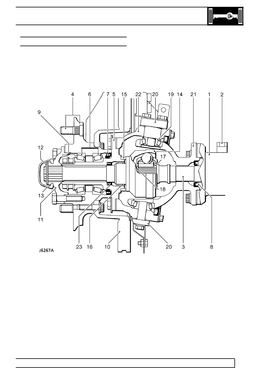
Front axle hub and swivel housing
1. Axle casing
2. Ventilation pipe
3. Axle shaft
4. Wheel studs and hub
5. Stub axle
6. Wheel bearings
7. Inner and outer hub seals
8. Axle shaft seal
9. Hub lock plate, thrust washer and nuts
10. Brake disc
11. Drive flange
12. Shim washer and circlip
13. Dust cap
14. Constant velocity joint/shaft
15. Thrust collar for CV joint
16. Roller bearing
17. Spacer
18. Circlip
19. Top and bottom swivel taper bearing
20. Top and bottom swivel pins
21. Spherical housing, seal and retainer
22. Swivel housing
23. Constant velocity shaft seal