
300Tdi Defender Fuel Injection Pump Page 206
19
FUEL SYSTEM
2
REPAIR
13. Remove banjo bolts securing spill return, main
fuel and boost signal pipes, refit banjo bolts after
disconnecting pipes.
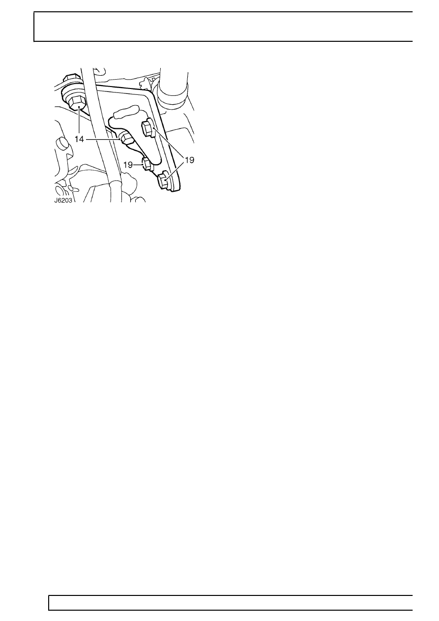
14. Remove 2 bolts securing rear of pump to
mounting bracket.
15. Remove 3 pump securing nuts at flange and
withdraw pump and gasket.
16. Fit suitable caps to pipe connections to prevent
ingress of dirt.
Refit
17. Clean mating faces of pump and front cover and
fit new gasket into position over pump mounting
studs.
18. Remove pump blanking plugs.
19. Slacken the 3 bolts, securing injection pump
mounting bracket to cylinder block, sufficiently
enough to allow bracket to move.
20. Fit pump to cover and secure with 3 nuts.
Tighten to
25 Nm (18 lbf/ft).
21. Loosely attach pump to mounting bracket with
nuts and bolts, then tighten bolts securing
bracket to cylinder block and bolts securing
pump to bracket, finger tight only.
22. To ensure correct fitting and alignment of
injection pump, first tighten the 2 bolts securing
pump to mounting bracket to
25 Nm (18 lbf/ft).
Then tighten the 3 bolts securing mounting
bracket to cylinder block, also to
25 Nm (18
lbf/ft).
23. Connect spill return and main fuel pipes and
secure with banjo bolts. Tighten to
25 Nm (18
lbf/ft).
24. Connect boost signal pipe and secure with banjo
bolt. Tighten to
10 Nm (7 lbf/ft).
25. Connect fuel cut-off solenoid lead and throttle
position sensor multi-plug, if fitted.
26. Connect throttle cable and where applicable,
hand throttle cable.
27. Remove pump gear retaining tool LRT-12-045.
28. Carefully turn the pump hub nut in a clockwise
direction, sufficiently enough to enable timing
tool pin to be inserted into injection pump.
29. Fit gear retaining plate and secure with 3 bolts.
Tighten to
25 Nm (18 lbf/ft).
30. Remove timing pin.
31. Ensure flywheel timing pin is disengaged from
slot in flywheel.
32. Turn crankshaft two complete revolutions, check
timing pin from RT-12-045 can be fully and
easily inserted into the pump. At the same time
check flywheel timing pin LRT-12-044 can also
be inserted in the flywheel slot.
33. If, with the flywheel timing pin located, the timing
pin cannot be inserted cleanly into the injection
pump, carry out the following:
a. Ensure flywheel timing pin is disengaged from
slot in flywheel.
b. Slacken the 3 pump gear retaining bolts.
c. Turn the pump hub nut in a clockwise
direction, sufficiently to enable timing tool pin to
be easily inserted into the injection pump.
d. Keeping the tension on the hub nut, check
that flywheel timing pin locates with slot in
flywheel.
e. Tighten the 3 pump gear retaining bolts to
25
Nm (18 lbf/ft).
f. Remove timing pins from pump and flywheel
housing.
34. Using a suitable anti-seize compound, fit the
blanking plug to flywheel housing. Tighten to
12
Nm (9 lbf/ft).
35. Fit access plate with gasket to front cover plate.
Tighten bolts to
25 Nm (18 lbf/ft).
36. Refit injector pipes.
37. Reconnect battery.