
300Tdi Defender
80
HEATING AND VENTILATION
2
DESCRIPTION AND OPERATION
HEATER OPERATION
The heater matrix (3), located in the distribution unit
(1), see J6341, is connected to the engine cooling
system. As water is circulated continuously through
the matrix, a selection of heated or ambient air is
controlled by two flaps within the distribution unit. The
temperature flap (12) controls the amount of ambient
air to the heater matrix, air being supplied
through a ducted vent on top of the vehicle front wing
to the blower motor (volute) housing (4). The blower
motor (10) can be used to boost the air flow into the
distribution unit. The air flap (13) controls the supply of
heated or ambient air from the heater unit into a
plenum chamber integeral with the vehicle fascia. Two
flaps in the plenum chamber (heater duct) distribute
the air flow to either the footwell vents or windscreen
demister vents as shown.
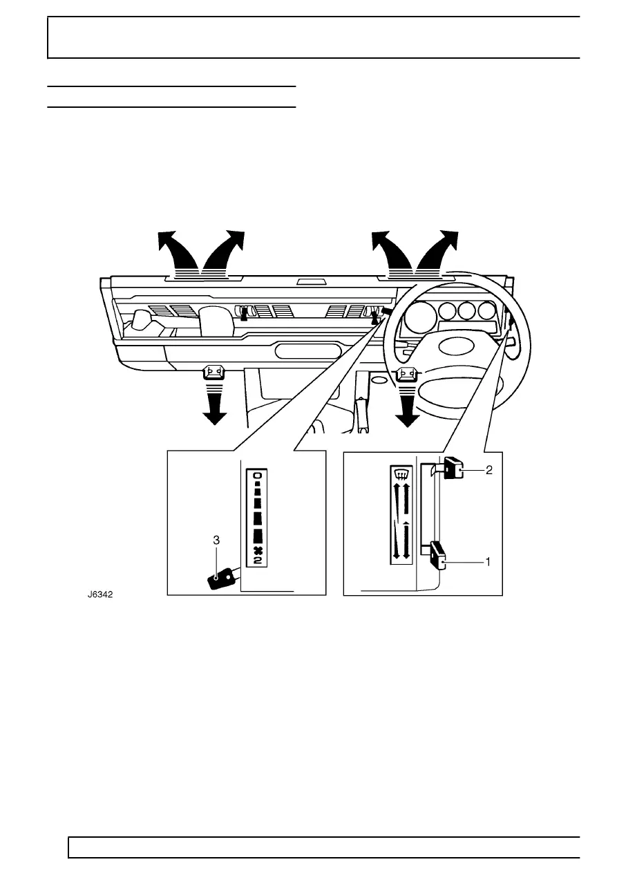
HEATER CONTROLS
1. Temperature control
Move the lever downwards to increase air
temperature or up to decrease air temperature.
2. Air distribution control
Lever fully up - windscreen vents only.
Lever midway - footwell and windscreen vents.
Lever fully down - footwell vents.
3. Blower motor fan speed control
Move the lever progressively downwards to increase
fan speed. With the control at ’0’ the fan is switched
off and the volume of air entering the passenger
compartment is solely dependent on ram air when the
vehicle is moving.