TD5 Defender EGR Modulator Maintenance and Upkeep

EMISSION CONTROL
9
DESCRIPTION AND OPERATION
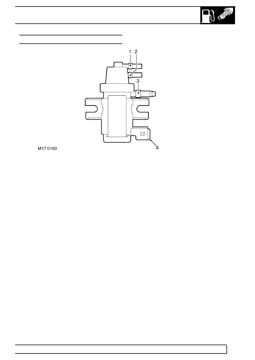
EGR MODULATOR
1. Port to vacuum source (white band)
2. Port to EGR valve (blue band)
3. Port to atmosphere via in-line filter (green band)
4. Harness connector
The EGR modulator is located on a plate fixed to the inner RH front wing. The modulator is attached to the plate
by two studs, each with two nuts which secure the assembly to a rubber mounting, which helps reduce noise. The
modulator must be mounted vertically with the two vacuum ports uppermost.
Modulator operation is controlled by a signal from the ECM which determines the required amount of EGR needed
in response to inputs relating to air flow, engine operation, and ambient conditions. The modulator has a two pin
connector at its base to connect it to the ECM via the engine harness.
The modulator features three ports:
•
The top port is identified by a white band and connects to a T-piece in the vacuum line via a small bore light
brown plastic hose. The two other ports on the T-piece connect to the vacuum line hoses of black vinyl tubing
between the vacuum pump and the brake servo assembly attached to the bulkhead. The vacuum pump end of
the tubing terminates in a rubber elbow, which gives a vacuum tight seal on the suction port of the vacuum
pump. The brake servo end of the tubing terminates with a non-return valve in a plastic housing which plugs
into the front face of the brake servo housing.
•
The middle port is identified by a blue band, and connects to the suction port on the EGR valve through a small
bore blue plastic hose.
•
The lower port is identified by a green band and connects to atmosphere through an in-line filter via a small
bore green plastic hose.
The blue and brown vacuum hoses are protected by corrugated plastic sheaths. The ends of the hoses are fitted
with rubber boots to ensure vacuum tight seals at the component ports.
