TD5 Defender

12
ENGINE
24
DESCRIPTION AND OPERATION
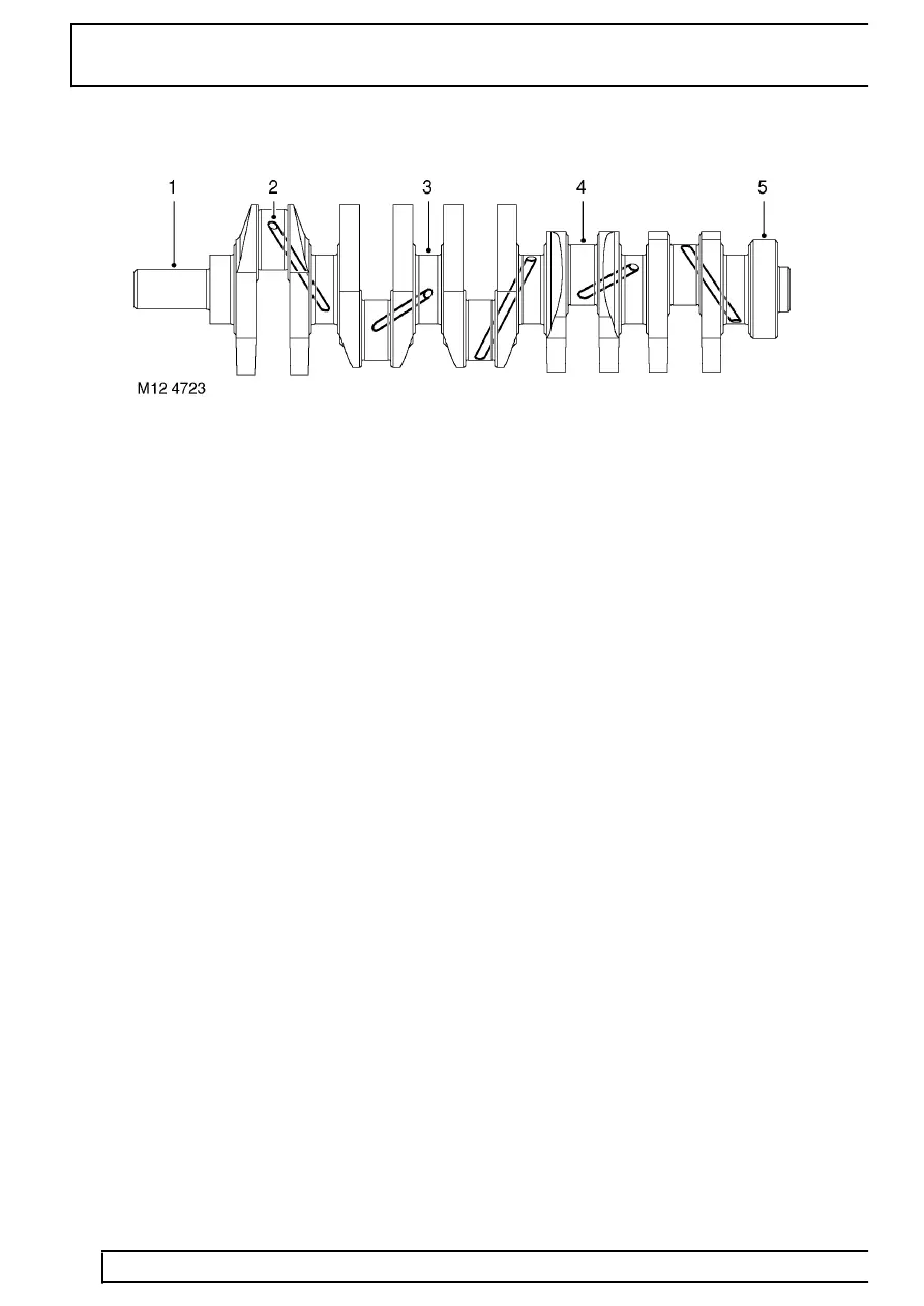
Crankshaft
1. Front end to crankshaft sprocket
2. Oil supply cross-drillings
3. Main journals
4. Big-end journals
5. Rear end to flywheel
The crankshaft is constructed from cast iron and is surface-hardened. The areas between the crankshaft journals
and the adjoining webs and balance weights are compressed using the cold roll process to form journal fillets.
Cross-drillings in the crankshaft between adjoining main and big-end bearings are used to divert lubrication oil to
the big-end bearings.
A torsional vibration damper is attached to the crankshaft pulley by three bolts.
The crankshaft is carried in six main bearings, with end-float being controlled by thrust washers positioned on both
sides of No. 3 main bearing.
Main bearings
There are six main bearings used to carry the crankshaft. Each of the bearing caps are of cast iron construction
and are attached to the cylinder block by two bolts.
The bearing shells are of the split cylindrical type. The upper half bearing shells are grooved to facilitate the supply
of lubrication oil to the bearings and fit into a recess in the underside of the cylinder block. The lower half bearing
shells are smooth and fit into the bearing caps.
Steel-backed, thrust washers are included at each side of No. 3 main bearing to control crankshaft end-float. One
side of each of the thrust washers is grooved, the grooved side of each of the thrust washers is fitted facing
outward from No. 3 main bearing.
