
Refinement of the ACE system
- Make
- Land Rover
- Model
- Discovery II Technical Bulletins
- Section
- Refinement of the ACE system › Refinement of the ACE system
REFINEMENT OF THE ACE SYSTEM
- Model
- Discovery Series II
- Affected vehicles
- All derivatives with Active Cornering Enhancement (ACE).
- Date
- 1999-04-28
- Reference
- Bulletin 0010, CDS ref L8533bu
Bulletin text
Discovery Series II
AFFECTED RANGE:
All derivatives with Active Cornering Enhancement (ACE).
PROBLEM:
REFINEMENT OF THE ACE SYSTEM
The customer complains of a noise / vibration which becomes more apparent during cornering, particularly at low engine speeds and / or when the vehicle is cold.
CAUSE:
Contact between ACE components and other parts of the vehicle, resulting in the amplification / transmission of normal hydraulic pump pulsations from the ACE system to the rest of the vehicle.
ACTION:
Inspect the vehicle for foul conditions between individual pipes and any chassis or body parts, noting the following key points: • = At no point should there be pipe to pipe contact between ACE system pipework or any other part of the vehicle. = • = No other component should be strapped to ACE pipework for support. = • = Any foul conditions which are detected should be carefully corrected BY HAND to give 5 - 10mm clearance with no small radii bends, kinks or damage. = • = At ‘P’ clip locations it may be necessary to remove, adjust and refit these so that the rubber isolators are not distorted and that the rubber shoulders are not deformed by the clip. = • = Pipes must not be forced into the clip locations, they must be reshaped BY HAND where necessary, to adopt a natural run through the clipping point.
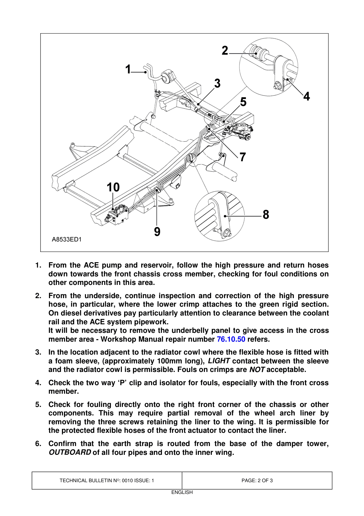
The following areas have been identified as those most likely to give rise to the concerns described. Where appropriate, the numbered items of text relate to the corresponding areas numbered in the illustration.
Bulletin N o : 0010 L8533bu 1 28.04.99
1. From the ACE pump and reservoir, follow the high pressure and return hoses down towards the front chassis cross member, checking for foul conditions on other components in this area. 2. From the underside, continue inspection and correction of the high pressure hose, in particular, where the lower crimp attaches to the green rigid section. On diesel derivatives pay particularly attention to clearance between the coolant rail and the ACE system pipework. It will be necessary to remove the underbelly panel to give access in the cross member area - Workshop Manual repair number 76.10.50 refers. 3. In the location adjacent to the radiator cowl where the flexible hose is fitted with a foam sleeve, (approximately 100mm long), LIGHT contact between the sleeve and the radiator cowl is permissible. Fouls on crimps are NOT acceptable. 4. Check the two way ‘P’ clip and isolator for fouls, especially with the front cross member. 5. Check for fouling directly onto the right front corner of the chassis or other components. This may require partial removal of the wheel arch liner by removing the three screws retaining the liner to the wing. It is permissible for the protected flexible hoses of the front actuator to contact the liner. 6. Confirm that the earth strap is routed from the base of the damper tower, OUTBOARD of all four pipes and onto the inner wing.
7. Check the four way ‘P’ clip and isolator inboard of the front right damper tower for correct installation. Also, check for fouls either side of the damper tower on the diagonal section of the pipe cluster. 8. Check the four way ‘P’ clip and isolator at the rear of the front right wheel arch. Also, ensure that there are no hard fouls between the chassis and the pipe cluster via the wiring harness or on the inner wing. 9. Inspect the section of pipework over the chassis outrigger to the valve block, ensuring there is no direct contact with chassis, body or wiring harness. 10. Ensure that no small stones or other road debris are trapped between the valve body and the chassis. 11. Inspect the final section of pipework between the valve block and the rear actuator as described for other pipework. 12. Confirm that the ACE pump is correctly fitted, as follows: • = Slacken all of the pump securing bolts. = • = Re - torque the uppermost pair of bolts to 25Nm. = • = Re - torque the lower bolt to 25Nm. = • = Restrain the pump pulley and slacken the three securing bolts. Re - torque to 25Nm.
If, after completion of the above, there is still a concern with the refinement of the ACE system, UK Dealers should contact Land Rover Technical Support. Overseas Dealers should contact their National Sales Company or Distributor Headquarters.
PARTS INFORMATION:
Not applicable
WARRANTY CLAIMS: Use Complaint Code: 5S1K
Use S.R.O.: 60.60.89/29 Time allowance: 0.70Hrs
This time includes an allowance for removing the underbelly panel and partial removal of the front wheel arch liner. These must not be claimed separately.
Parts & tools for this job For Land Rover Discovery
- TOOLCoil spring compressorSearch: coil spring compressor
- TOOLBall joint separatorSearch: ball joint separator
- PARTShock absorbersSearch: Land Rover Discovery shock absorbers
Links open Amazon search results in a new tab. As an Amazon Associate I earn from qualifying purchases.