Discovery II

AIR CONDITIONING
82-4
DESCRIPTION AND OPERATION
Refrigerant system
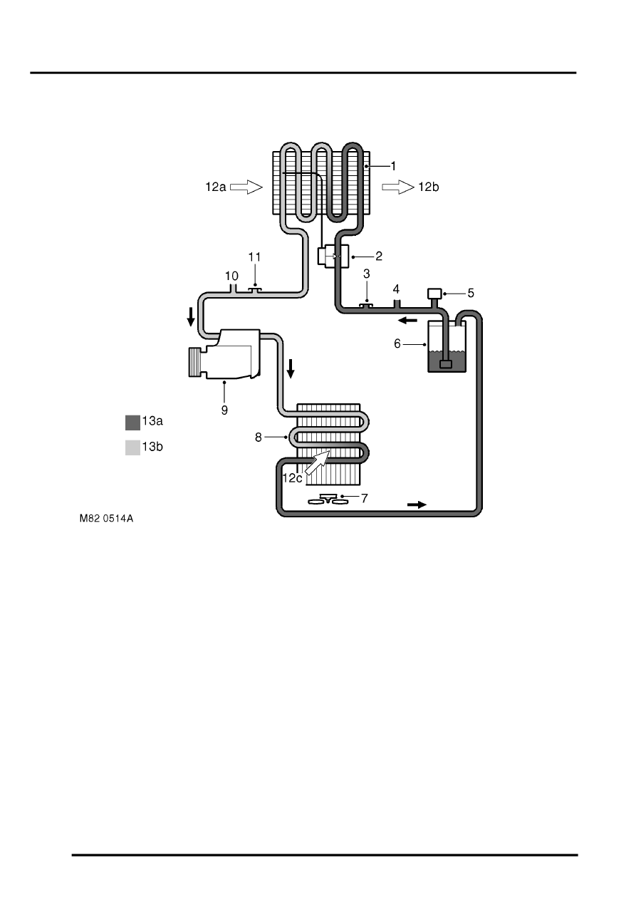
Schematic of air conditioning system
1 Evaporator
2 Thermostatic expansion valve
3 Low pressure servicing connection
4 Outlet to rear A/C system (where fitted)
5 Dual pressure switch
6 Receiver drier
7 Cooling fan
8 Condenser
9 Compressor
10 Inlet from rear A/C system (where fitted)
11 High pressure servicing connection
12 Air flows
a Ambient air
b Cooled air
c Ambient air through condenser
13 Refrigerant
a Liquid
b Vapour
The refrigerant system transfers heat from the vehicle interior to the outside atmosphere to provide the heater
assembly with dehumidified cool air. The system comprises a compressor, condenser, receiver drier, thermostatic
expansion valve and evaporator, joined together by refrigerant lines. The system is a sealed, closed loop, filled with
a charge weight of R134a refrigerant as the heat transfer medium. Oil is added to the refrigerant to lubricate the
internal components of the compressor.
To accomplish the transfer of heat, the refrigerant is circulated around the system, where it passes through two
pressure/temperature regimes. In each of the pressure/temperature regimes, the refrigerant changes state, during
which process maximum heat absorption or release occurs. The low pressure/temperature regime is from the
thermostatic expansion valve, through the evaporator to the compressor; the refrigerant decreases in pressure and
temperature at the thermostatic expansion valve, then changes state from liquid to vapour in the evaporator, to absorb
heat. The high pressure/temperature regime is from the compressor, through the condenser and receiver drier to the
thermostatic expansion valve; the refrigerant increases in pressure and temperature as it passes through the
compressor, then releases heat and changes state from vapour to liquid in the condenser.
