Discovery II

AUTOMATIC GEARBOX - ZF4HP22 - 24
44-14
DESCRIPTION AND OPERATION
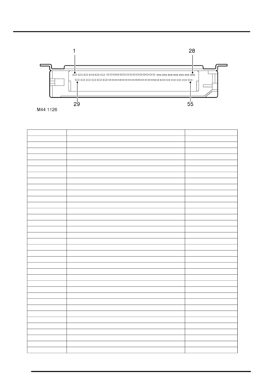
EAT ECU connector
EAT ECU connector pin details
Pin No.
Description
Inputs/Outputs
1 to 4
Not used
-
5
Pressure regulator solenoid valve (MV 4)
Output
6
Power earth
-
7
Not used
-
8
Gear position switch, X contacts
Input
9
Gear position switch, Z contacts
Input
10 to 12
Not used
-
13
Transmission high/low switch
Input
14
Gearbox output shaft speed sensor, negative
Input
15
Gearbox output shaft speed sensor cable screen
-
16
CAN, high
Input/Output
17 to 24
Not used
-
25
Sport mode warning lamp
Output
26
Battery power supply
Input
27
Not used
-
28
Electronics earth
-
29
Not used
-
30
Shift control solenoid valve (MV 1)
Output
31
Diagnostics, K line
Input/Output
32
Converter lock-up solenoid valve (MV 3)
Output
33
Shift control solenoid valve (MV 2)
Output
34
Not used
-
35
Not used
-
36
Gear position switch, W contacts
Input
37
Gear position switch, Y contacts
Input
38 to 41
Not used
-
42
Gearbox output shaft speed sensor, positive
Input
43
Not used
-
44
CAN, low
Input/Output
45
Mode switch
Input
46 to 50
Not used
-
51
Manual mode warning lamp
Output
52
Not used
-
53
Solenoid valves power supply
Output
54
Ignition power supply
Input
55
Not used
-
