
Discovery II
BODY CONTROL UNIT
86-3-16 DESCRIPTION AND OPERATION
Cruise control
The BCU processes several signals used for cruise control:
l
When the brake pedal is pressed, a low voltage brake lamp signal is sent via the BCU to the cruise control ECU.
l
The gear position switch sends an input via the BCU to the cruise control ECU if the selector lever is in Park,
Neutral or Reverse.
l
A voltage supply is fed from the BCU to the cruise control SET+ switch.
l
A voltage supply is fed from the BCU to the cruise control RES switch.
On vehicles with automatic transmission, if the BCU receives an input from the gear position switch or the brake pedal
switch, the BCU sends a signal to the cruise control ECU to cancel or inhibit cruise control operation.
ENGINE MANAGEMENT SYSTEM - Td5, DESCRIPTION AND OPERATION, Description.
ENGINE MANAGEMENT SYSTEM - V8, DESCRIPTION AND OPERATION, Description - cruise control.
Shift interlock (where fitted)
On automatic gearbox models, the BCU and IDM combine with an interlock relay located in the passenger
compartment fuse box to operate a shift interlock solenoid, so that the gear selector lever cannot be moved out of
Park until certain logical conditions have been satisfied. Operation of the interlock may be affected, if the battery
becomes discharged.
AUTOMATIC GEARBOX - ZF4HP22 - 24, DESCRIPTION AND OPERATION, Description.
Ignition key interlock (where fitted)
On automatic gearbox models, the ignition key interlock solenoid prevents removal of the ignition key from the ignition
switch when the transmission gear selector is not in the Park position. The logic control operation for this is performed
by the BCU.
Transfer box interlock (where fitted)
On automatic gearbox models, a transfer box interlock solenoid is controlled by the IDM to prevent transfer box shift
lever being moved out of high or low range unless certain conditions have been satisfied. The IDM controls the
operation of the transfer box relay which is located in the passenger compartment fuse box.
TRANSFER BOX - LT230SE, DESCRIPTION AND OPERATION, Description.
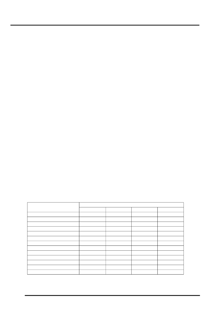
Gear position switch
A gear position switch is located on the automatic gearbox and is used to inform the BCU of the gear selector lever
position. The BCU has four sensing inputs from the gear position switch contacts W, X, Y, Z, which are used to
determine the gearbox drive status at any particular instance. The BCU gives an output corresponding to the gearbox
status derived from the gear position switch inputs. The logic states defining the gear selector positions are listed in
the table below, where Z1, Z2, Z3 and Z4 represent intermediate states which exist as the selector lever position is
changed:
Gear position
Switch contacts
W
X
Y
Z
P (Park)
1
0
0
0
Z1
1
1
0
0
R (Reverse)
0
1
0
0
Z1
1
1
0
0
N (Neutral)
1
1
1
0
Z2
1
0
1
0
D (Drive)
1
0
1
1
Z3
1
1
1
1
3
0
1
1
1
Z4
0
0
1
1
2
0
0
0
1
Z4
0
0
1
1
1
0
0
1
0