Discovery II

BRAKES
DESCRIPTION AND OPERATION
70-5
Description
General
The brakes consist of front and rear disc brakes operated by a diagonally split, dual circuit hydraulic system with
vacuum servo power assistance. The system incorporates the following control functions as standard on all models:
l
Anti-lock Brakes (ABS), to prevent road wheels locking during brake application.
l
Electronic Brake Distribution (EBD), to control distribution of hydraulic pressure between front and rear axles.
Replaces mechanical pressure limiting valve of previous systems.
l
Electronic Traction Control (ETC), to maintain even torque distribution to the road wheels.
l
Hill Descent Control (HDC), to provide controlled descent ability in off road conditions.
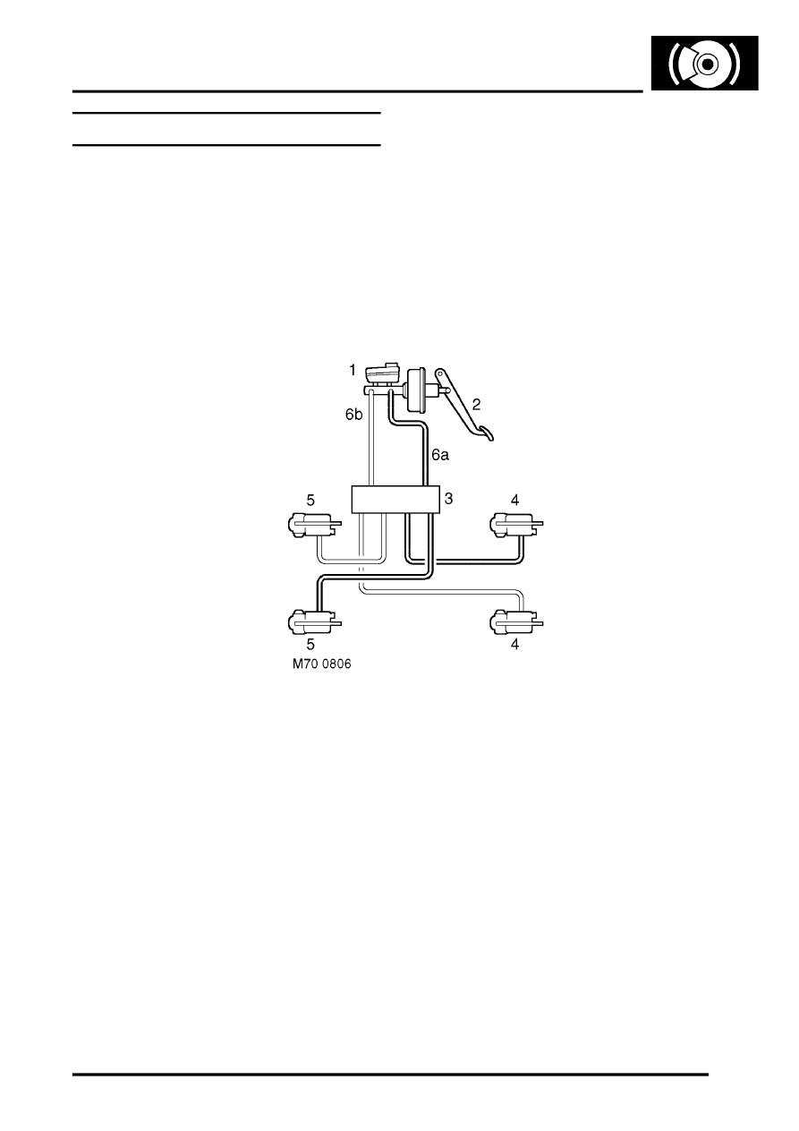
Hydraulic system schematic
1 Master cylinder/brake servo assembly
2 Brake pedal
3 ABS modulator
4 Rear brake
5 Front brake
6 Hydraulic circuit
a Primary
b Secondary
For normal brake operation, brake pedal movement is assisted by the brake servo assembly and transmitted to the
master cylinder assembly. The master cylinder assembly converts brake pedal movement to hydraulic pressure.
Primary and secondary brake pipe circuits supply the hydraulic pressure to the brakes via the ABS modulator: the
primary circuit supplies the front left and rear right brakes; the secondary circuit supplies the front right and rear left
brakes. Vacuum for the brake servo assembly is obtained from the engine inlet manifold (V8 models) or a vacuum
pump (diesel models), through a vacuum line and non return valve. To reduce operating noise, sleeving is installed
on some of the brake pipes in the engine compartment and the pipes are located in sprung pipe clips.
For all control functions, the ABS modulator regulates the hydraulic pressure to the brakes to control the speed of all
four wheels, either individually or in axle pairs. Operation of the ABS modulator is controlled by the Self Levelling and
Anti-lock Braking Systems (SLABS) ECU. The SLABS ECU also operates warning indications in the instrument pack
to provide the driver with status information on each function.
