
Discovery II
EMISSION CONTROL - V8
17-2-34 DESCRIPTION AND OPERATION
Crankcase Emission Control Operation
Oil laden noxious gas in the engine crankcase is drawn through a spiral oil separator located in the stub pipe to the
ventilation hose on the right hand cylinder head rocker cover, where oil is separated and returned to the cylinder head.
The rubber ventilation hose from the right hand rocker cover is routed to a port on the right hand side of the inlet
manifold plenum chamber, where the returned gases mix with the fresh inlet air passing through the throttle butterfly
valve. The stub pipe on the left hand rocker cover does not contain an oil separator, and the ventilation hose is routed
to the throttle body housing at the air inlet side of the butterfly valve. The mass of fresh air which is drawn in from the
atmospheric side of the throttle butterfly to mix with the returned crankcase gas depends on the throttle position and
the engine speed.
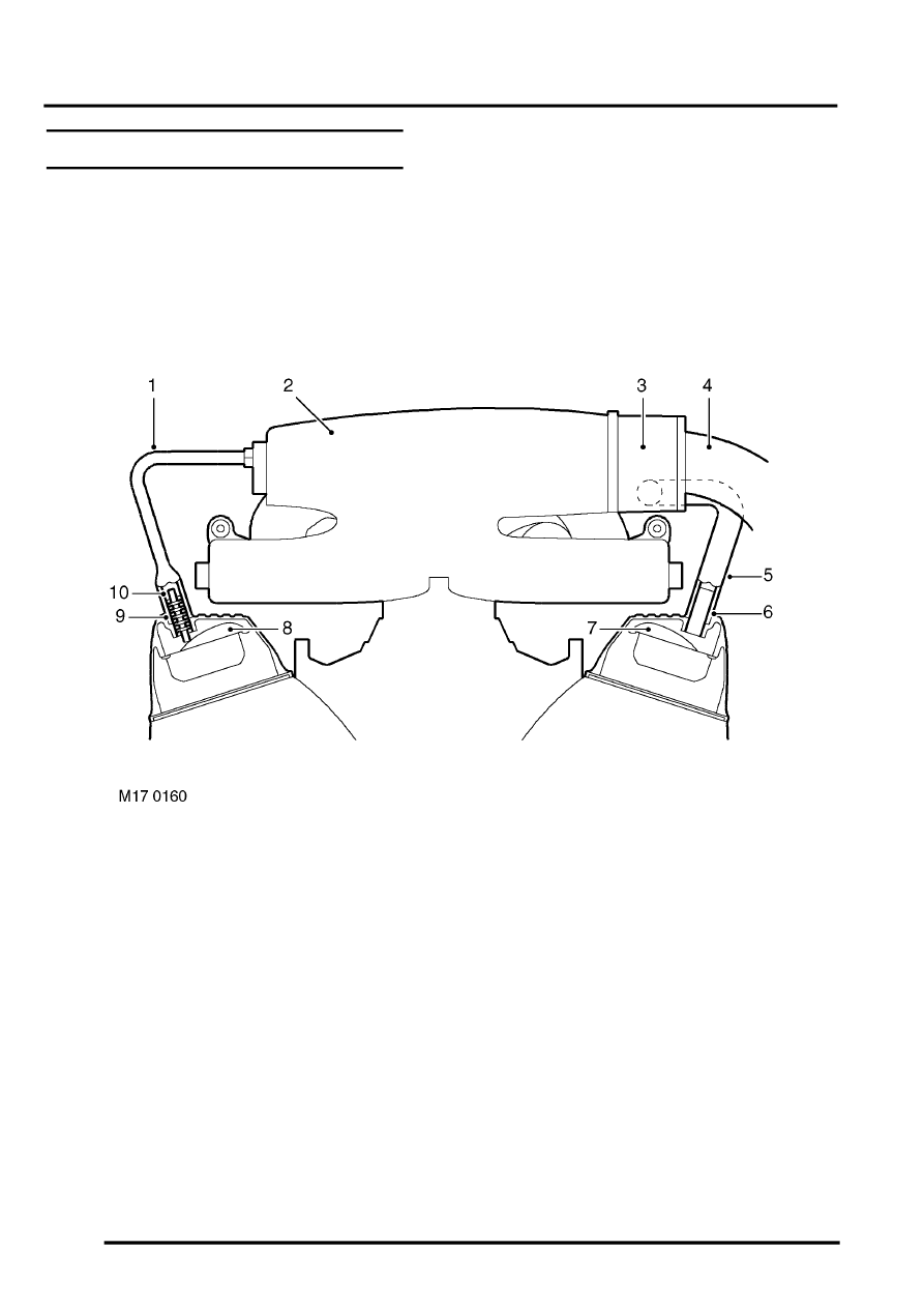
1 Hose – RH rocker cover to inlet manifold
2 Inlet manifold
3 Throttle body
4 Air intake
5 Hose – LH rocker cover to inlet manifold
6 LH rocker cover breather tube
(without oil separator)
7 LH rocker cover baffle
8 RH rocker cover baffle
9 RH rocker cover breather tube
10 Oil separator (integral with breather tube)
When the engine is running in cruise conditions or at idle, manifold pressure is low and the majority of gases are drawn
into the inlet manifold through the oil / vapour separator in the RH rocker cover stub pipe. At the same time, filtered
air is drawn from the throttle body into the engine via the LH rocker cover.
During periods of driving at Wide Open Throttle (WOT), pressure at either side of the throttle disc equalizes (manifold
depression collapses). The larger ventilation opening at the throttle housing positioned in the fast moving stream of
intake air, now offers more 'pull' than the small opening in the RH rocker cover and the flow of ventilation reverses,
drawing gases from the LH rocker cover into the throttle body for subsequent burning in the combustion chambers.