
Discovery II
EMISSION CONTROL - V8
DESCRIPTION AND OPERATION
17-2-5
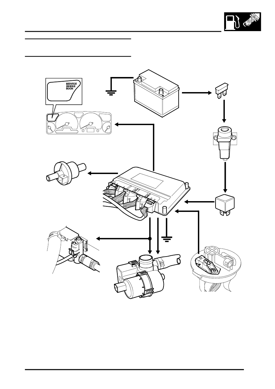
Evaporative emission system control
diagram
1 Battery
2 Fuse 13 (engine compartment fusebox)
3 Inertia switch
4 Main relay (engine compartment fusebox)
5 Engine Control Module (ECM)
6 Purge Valve (black harness connector)
7 Canister vent solenoid (CVS) valve – NAS
vehicles with vacuum type EVAP system leak
detection capability only
8 Leak detection pump – NAS vehicles with
positive pressure type EVAP system leak
detection capability only
9 Fuel tank pressure sensor – NAS vehicles with
vacuum type EVAP system leak detection
capability only
10 Instrument pack (MIL warning light)
M17 0210
1
2
3
4
5
6
7
9
8
10