Discovery II

FRONT AXLE
DESCRIPTION AND OPERATION
54-3
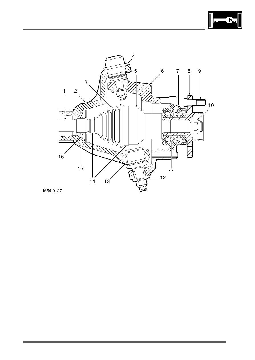
Wheel hub
Section through wheel hub
1 Drive shaft
2 Axle casing
3 Gaiter
4 Upper ball joint
5 Constant velocity joint
6 Steering knuckle
7 Hub bearing
8 Hub flange
9 Wheel stud
10 Stake nut
11 ABS sensor ring
12 Tension collet
13 Lower ball joint
14 Securing bands
15 Shield
16 Oil seal
Each wheel hub consists of a hub flange pressed into a hub bearing.
The hub flange is splined to accept the constant velocity joint of the drive shaft, which is secured to the hub flange
with a stake nut. Five studs are installed in the hub flange for the wheel nuts and a threaded hole is provided for the
brake disc securing screw.
The outer race of the hub bearing is bolted to the steering knuckle. The hub bearing is a sealed unit which contains
twin opposed roller bearings, pre-packed with grease during manufacture. A toothed ABS sensor ring is integrated
into the inner race of the hub bearing. An opening in the outer race of the hub bearing accommodates the ABS sensor.
Drive shaft
Each drive shaft consists of a solid rod, splined at both ends, with a constant velocity joint installed on the outboard
end. A shield is incorporated onto each rod to protect the oil seals in the axle casing. The constant velocity joint is of
the ball and socket type. A shaft on the constant velocity joint is splined to the hub flange. The constant velocity joint
is pre-packed with grease and protected by a gaiter. Two securing bands retain the gaiter in position.
