Discovery II

FRONT SUSPENSION
60-16
DESCRIPTION AND OPERATION
Torsion bar
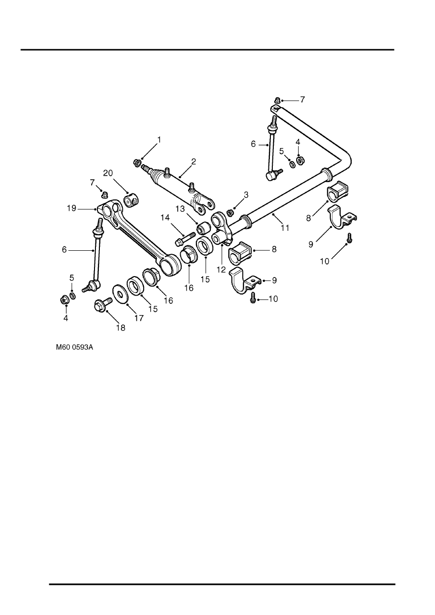
Front torsion bar shown, rear torsion bar similar
1 Locknut
2 Actuator
3 Locknut
4 Locknut 2 off
5 Washer
6 Anti-roll bar link
7 Locknut
8 Bush
9 Clamp plate
10 Bolt 2 off
11 Torsion bar
12 Short arm
13 Bush
14 Bolt
15 Outer slipper bush 2 off
16 Inner slipper bush 2 off
17 Washer
18 Bolt
19 Long arm
20 Bush
The front and rear torsion bar assemblies are similar in their construction, the rear torsion bar being narrower than the
front. Each torsion bar is made from 35 mm (1.38 in.) diameter spring steel bar.
The right hand end of the torsion bar has a machined spigot which provides for the attachment of the forged steel
short and long arms. The spigot for the short arm is splined and mates with splines in the short arm. The short arm is
located in a specific position on the splines and clamped to the spigot with a Torx bolt and locknut. The short arm is
not a serviceable item other than the actuator attachment bush. The smaller spigot diameter locates the long arm.
The long arm is fitted with a slipper bush which is located on the spigot and secured with a large washer and a special
bolt. The slipper bush comprises two inner and two outer bushes which are installed from each side of the long arm.
The outer bushes have three lugs which locate in the long arm to prevent the bush from rotating. The long arm also
provides the attachment point for the actuator piston rod and the anti-roll bar link.
