
Discovery II
FRONT SUSPENSION
DESCRIPTION AND OPERATION
60-19
When system faults are detected by the ECU, the ACE warning lamp in the instrument pack is illuminated by the ECU
continuously in amber for minor faults or flashing red with an audible warning for faults which require the driver to stop
the vehicle immediately.
The ACE ECU supplies a control current to the pressure control valve in the valve block. The current supplied by the
ECU is determined by a number of input signals from the upper and lower accelerometers, road speed etc.. The
pressure control valve controls the hydraulic pressure supplied to the actuators proportional to the current supplied
by the ECU.
Power is supplied to the two solenoid operated directional control valves (DCV's) in the valve block by the ECU.
Together, the DCV's control the direction of flow of hydraulic fluid to the actuators. When the ECU supplies power to
the solenoids the valves open allowing hydraulic fluid to flow to the actuators. When power is removed the valves
close.
The pressure transducer in the valve block receives a 5 V supply from the ECU. The pressure transducer measures
hydraulic pressures in the range of 0 to 180 bar (0 to 2610 lbf.in
2
) and returns a linear output voltage to the ECU
dependent on hydraulic pressure.
The ECU supplies a 5 V current to each of the accelerometers. Each accelerometer is capable of measuring lateral
acceleration in the range of
±
1.10 g. An analogue input to the ECU of between 0.5 and 4.5 V relative to the lateral
acceleration sensed is returned by each accelerometer. The ECU processes the two signals received to produce a
'pure' lateral acceleration signal which is then used as the main control signal for the ACE system.
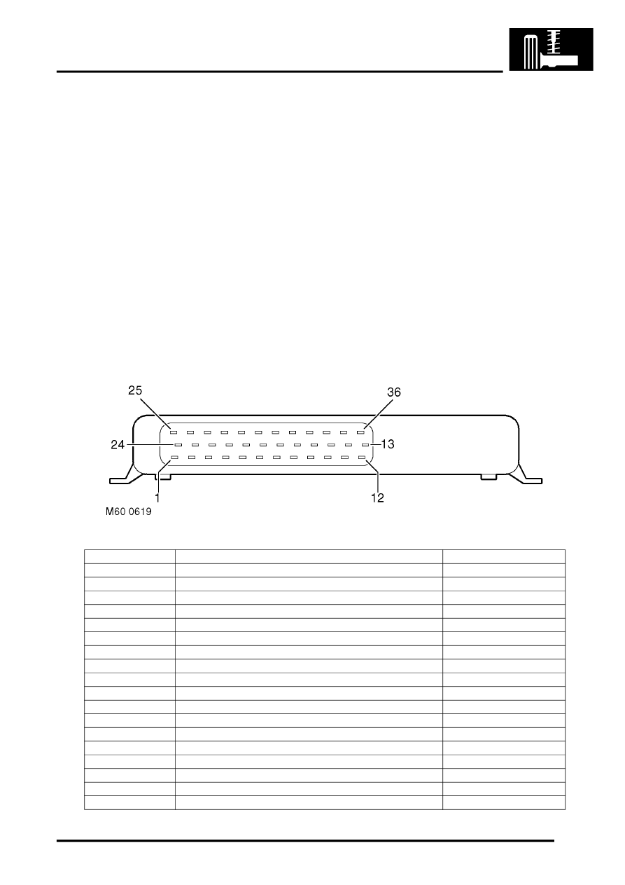
ACE ECU connector pin details
Pin No.
Description
Input/Output
1
Not used
-
2
Not used
-
3
Spare
Input
4
Not used
-
5
Road speed
Input
6
ARC relay
Output
7 to 9
Not used
-
10
K line (diagnostics)
-
11
Ignition switch
Input
12
Accelerometer - lower (supply)
Output
13
Pressure transducer (supply)
Output
14
Reverse switch
Input
15
Accelerometer - lower (signal)
Input
16
Pressure transducer (signal)
Input
17
Accelerometer - upper (signal)
Input
18
Accelerometer - upper (supply)
Output
19
Engine speed
Input
20
Main earth 1
-