
FRONT SUSPENSION (Operation): DESCRIPTION AND OPERATION
- Make
- Land Rover
- Model
- Discovery II
- Section
- DESCRIPTION AND OPERATION › Operation
FRONT SUSPENSION
60-22
DESCRIPTION AND OPERATION
Operation
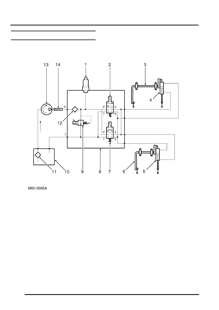
Hydraulic circuit diagram
1 Pressure transducer
2 Directional control valve 2
3 Front torsion bar assembly
4 Actuator
5 Actuator
6 Rear torsion bar assembly
7 Directional control valve 1
8 Valve block
9 Pressure control valve
10 Reservoir
11 Filter
12 High pressure filter
13 Hydraulic pump
14 Attenuator hose
Vehicle not moving
When the engine is running and the vehicle is not moving, both DCV's are closed, locking fluid in each side of the
actuator pistons. The hydraulic pump draws fluid from the reservoir and passes it at very low pressure to the valve
block. Because both DCV's are closed, after the fluid passes through the high pressure filter, it is directed through the
pressure control valve to the reservoir. The pressure control valve is open fully to allow the full flow to pass to the
reservoir. The DCV's will remain closed until the ECU detects a need to operate.
Parts & tools for this job For Land Rover Discovery
- TOOLCoil spring compressorSearch: coil spring compressor
- TOOLBall joint separatorSearch: ball joint separator
- PARTFront shock absorbersSearch: Land Rover Discovery front shock absorbers
Links open Amazon search results in a new tab. As an Amazon Associate I earn from qualifying purchases.