Discovery II

GENERAL INFORMATION
03-22
Rotary coupler
Always follow the Repair procedure for fitting the
rotary coupler.
Comply with all safety and installation procedures to
ensure the system functions correctly. Observe the
following precautions:
l
Do not install a rotary coupler if it is suspected to
be defective.
l
Do not attempt to service, modify or repair a
rotary coupler.
l
Do not cut, splice or modify the wires attached
to yellow SRS connector and lead.
l
Always ensure the rotary coupler connectors
are mated correctly and securely fastened.
l
Always ensure the battery is disconnected
before working on the rotary coupler.
l
Always ensure the rotary coupler is removed
and installed in its centered position and with the
front road wheels in the straight ahead position.
l
If a new rotary coupler is being installed, ensure
the locking tab holding the coupler's rotational
position is not broken; units with a broken
locking tab should not be used.
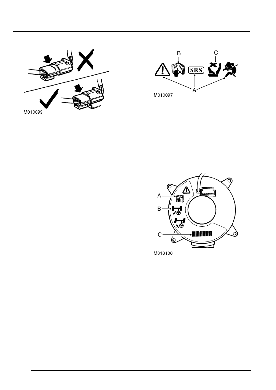
Warning labels
Warning symbols are displayed at various positions
in the vehicle (either in a suitable prominent position
such as driver and passenger side glass, or attached
to the component itself) to indicate SRS items which
must be treated with particular care. Exact positions
of SRS warning labels may vary dependent on
legislation and market trends.
WARNING: It is imperative that before any work
is undertaken on the SRS system the appropriate
information is read thoroughly.
Side window label
a The need for caution when working in close
proximity to SRS components.
b Refer to the publication where the procedures,
instructions and advice can be found (usually
the Workshop Manual) for working on the SRS
system.
c Do not use rear facing child seats in the front
passenger seat if the vehicle is fitted with a
passenger airbag.
Rotary coupler label
a Refer to the Workshop Manual for detailed
instructions
b Ensure wheels are in the straight ahead
position before removal and refitting
c Part number/Bar code. The code must be
recorded and quoted for ordering purposes
