
Discovery II
HEATING AND VENTILATION
DESCRIPTION AND OPERATION
80-9
FBH fuel pump
The FBH fuel pump regulates the fuel supply to the FBH unit. The FBH fuel pump is installed in a rubber mounting on
the chassis crossmember immediately in front of the fuel tank. The pump is a self priming, solenoid operated plunger
pump, with a fixed displacement of 0.063 ml/Hz. The ECU in the FBH unit outputs a pulse width modulated signal to
control the operation of the pump. When the pump is de-energised, it provides a positive shut-off of the fuel supply to
the FBH unit.
FBH fuel pump nominal operating speeds/outputs
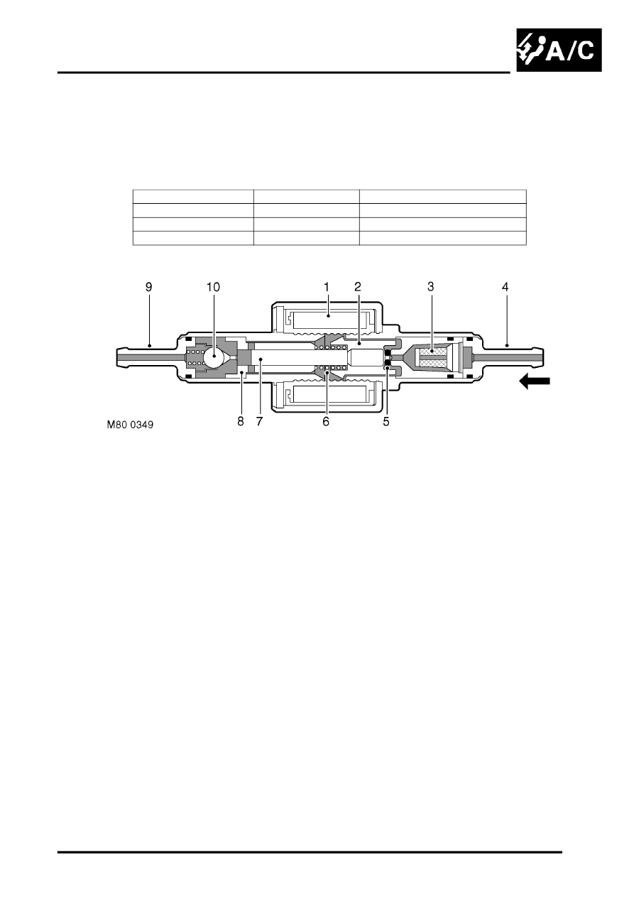
Sectioned view of FBH fuel pump
1 Solenoid coil
2 Plunger
3 Filter insert
4 Fuel line connector
5 'O' ring seal
6 Spring
7 Piston
8 Bush
9 Fuel line connector
10 Non return valve
The solenoid coil of the FBH fuel pump is installed around a housing which contains a plunger and piston. The piston
locates in a bush, and a spring is installed on the piston between the bush and the plunger. A filter insert and a fuel
line connector are installed in the inlet end of the housing. A non return valve and a fuel line connector are installed
in the fuel outlet end of the housing.
While the solenoid coil is de-energised, the spring holds the piston and plunger in the 'closed' position at the inlet end
of the housing. An 'O' ring seal on the plunger provides a fuel tight seal between the plunger and the filter insert,
preventing any flow through the pump. When the solenoid coil is energised, the piston and plunger move towards the
outlet end of the housing, until the plunger contacts the bush, and draw fuel in through the inlet connection and filter.
The initial movement of the piston also closes transverse drillings in the bush and isolates the pumping chamber at
the outlet end of the housing. Subsequent movement of the piston then forces fuel from the pumping chamber through
the non return valve and into the line to the FBH unit. When the solenoid coil de-energises, the spring moves the piston
and plunger back towards the closed position. As the piston and plunger move towards the closed position, fuel flows
passed the plunger and through the annular gaps and transverse holes in the bush to replenish the pumping chamber.
Operating phase
Speed, Hz
Output, l/h (US galls/h)
Start sequence
0.70
0.159 (0.042)
Part load
1.35
0.306 (0.081)
Full load
2.70
0.612 (0.163)