Discovery II

REAR SUSPENSION
DESCRIPTION AND OPERATION
64-15
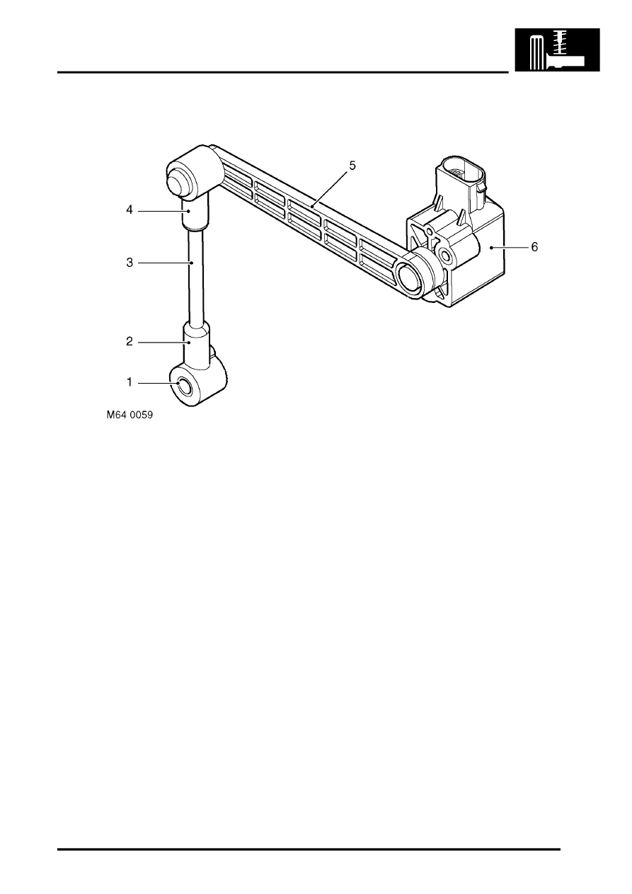
Height sensors
1 Spacer
2 Link end
3 Link
4 Link end
5 Arm
6 Sensor body
Two height sensors are located on the outside of each chassis longitudinal forward of the rear axle. Each sensor body
is attached to a fabricated bracket and secured with two screws. The sensor is attached to the top of each radius arm
by an arm, a link and two link ends. The link ends allow articulation of the arm to allow for suspension travel. The lower
link arm is attached to a lug of the top of the radius arm and is secured with a bolt and locknut.
The sensor body and arm are manufactured from moulded nylon. The two link ends are made from natural rubber
and the link is made from mild steel. The rubber link ends allow flexibility of the arm and resistance to damage.
Each sensor is connected to the main chassis harness by a multiplug. The three pin multiplug provides an earth, a 5
V supply voltage and an output signal voltage to the SLABS ECU.
Each sensor operates on the Hall effect principle. A magnet is attached to the shaft and rotates with movement of the
arm. The magnetic flux generated acts on a Hall effect sensor and depending on its position varies the current across
the sensor. This current is measured and amplified and passed to the SLABS ECU as a linear output voltage signal,
which varies depending on the angular position of the sensor. The signal information is processed and the ECU can
determine the vehicle height.
When the sensors are replaced or removed for any reason, a calibration procedure is required to recalibrate the
sensors and the SLABS ECU. The calibration procedure requires the use of TestBook and calibration blocks to set
the axle to chassis height to a known value.
If faults occur with the height sensors, fault codes are stored in the SLABS ECU. The current and past fault codes can
be retrieved with TestBook.
