Discovery II

REAR SUSPENSION
DESCRIPTION AND OPERATION
64-17
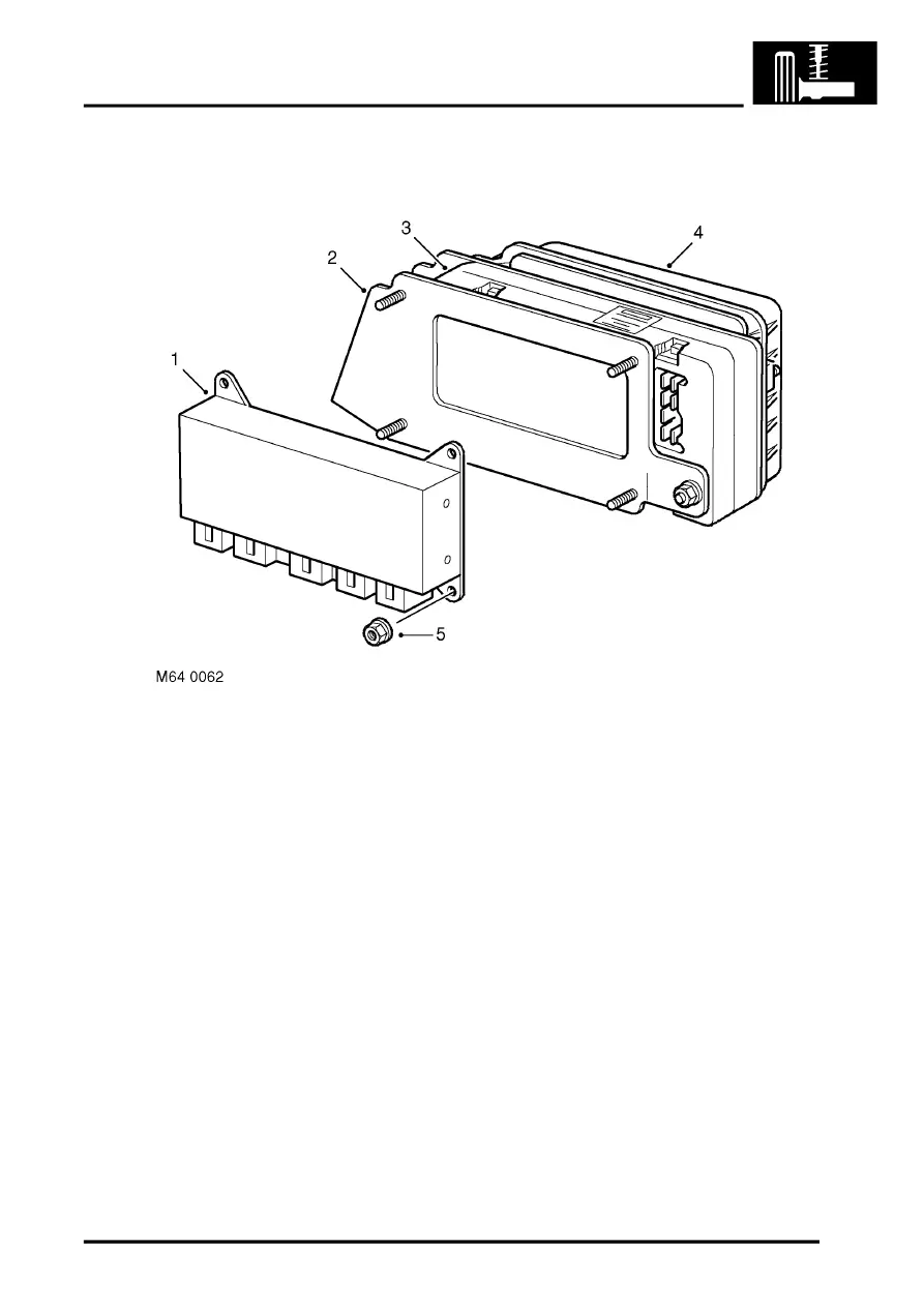
SLABS ECU
1 SLABS ECU
2 Bracket
3 BCU (Ref. only)
4 ACE ECU (Ref. only)
5 Attachment nuts
The SLABS ECU is mounted on a bracket behind the passenger glove box and is identified from the other ECU's by
its five connectors. The five connectors are located on the lower face of the ECU and mate with five connectors from
the main harness. The twelve, six and eighteen pin connectors are used to supply inputs and outputs to and from the
ECU. The remaining connectors are used for the ABS operation.
BRAKES, DESCRIPTION AND OPERATION, Description.
The SLABS ECU receives a continuous battery supply from fuse 11 in the engine compartment fusebox. An ignition
'ON' signal is supplied from the ignition switch via fuse 28 in the passenger compartment fusebox. The ECU has the
ability to control when it requires power and is not reliant on the ignition signal for it to power up.
The ECU incorporates a counter which times the operation of the SLS system and prevents the compressor
exceeding its duty cycle. The ECU can remain powered for up to 1.5 hours after ignition off is sensed to allow the
counter to continue running to avoid an ignition cycle resetting the counter.
Opening any of the doors will power up the ECU, irrespective of ignition switch position. The door open signal is
sensed by the door switch completing an earth path which is sensed by the ECU. The ECU cannot differentiate
between any of the doors. The door open signal powers the ECU for up to 30 minutes to allow the vehicle to re-level
when a load is removed or passengers leave the vehicle.
The ECU supplies a 5 V current to each of the height sensors. Each height sensor uses the current to supply an
analogue input to the ECU. The ECU can calculate from the input received from each height sensor the height of the
vehicle and can then power the air supply unit as necessary to raise or lower one or both air springs to level the
vehicle.
