
Discovery II
REAR SUSPENSION
DESCRIPTION AND OPERATION
64-7
Coil Spring Specifications – Models up to 03 Model Year
The rear coil springs are of the variable rate type and are manufactured from silicon manganese 16.5 mm (0.65 in.)
diameter bar. Each spring has 9 coils and a free length of 385 mm (15.1 in.). The variable rate of the spring is achieved
by the active coils at one end being closer together. The rear coil spring is identified by a purple stripe painted on a
number of coils.
Coil Spring Specifications – Models From 03 Model Year
The introduction of the 03MY vehicle introduced a range of additional rear coil spring fitments. These were introduced
as a package to optimise vehicle trim heights.
The coil springs are manufactured from silicon manganese 16.35 mm (0.64 in.) diameter bar for springs on five seater
models and 16.57 mm (0.65 in.) diameter bar on seven seater models. The following spring data table shows the
colour codes, number of coils and spring free length.
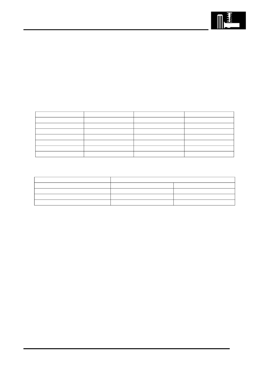
Spring Data
The following table shows spring fitment applicability.
Spring Fitment Applicability
Watts linkage
A Watts linkage is used to ensure that the rear axle remains centrally located. The Watts linkage comprises two
transverse links and a pivot housing. The transverse links and pivot housing allow the rear axle to move vertically
without any transverse movement.
The transverse links are made from fabricated and welded steel. Each transverse link has a bush press fitted into a
housing at one end. The opposite end has a forked bracket with two cross holes.
The pivot housing is made from cast iron. Three bushes are press fitted in the housing, one in the centre and one at
each end.
The pivot housing is located in a fabricated bracket centrally located on the rear of the axle. The central bush of the
pivot housing is secured in the bracket with a bolt and locknut. Fabricated brackets on each chassis longitudinal
provide for the attachment of each transverse link. Each link is secured through its bush with a bolt and locknut. The
forked end of each link locates over the bushes at each end of the pivot housing and is secured with a bolt and locknut.
The attachment bolts for each link are coated with a clear, dry wax which reduces friction on the bolt and allows the
correct torque to be applied to the clamping of the bushes. The bolts can be re-used, but if bolt replacement is
necessary the correct bolt with the wax coating must be used.
Colour Code
Total No. of Coils
Free Length
Model
Brown/Orange
8.73
384.7 mm (15.14 in)
5 Seat
Grey/Orange
8.73
392 mm (15.43 in)
5 Seat
Yellow/Grey
8.73
376.6 mm (14.82 in)
5 Seat
Pink/Grey
8.73
400.3 mm (15.75 in)
5 Seat
Blue/Grey
9.10
387.8 mm (15.26 in)
7 Seat
Green/Grey
9.10
395.2 mm (15.55 in)
7 Seat
White/Grey
9.10
380.6 mm (14.98 in)
7 Seat
Left Hand Drive
Right Hand Drive
Both Sides
RH Side
LH Side
Brown/Orange
Grey/Orange
Yellow/Grey
Grey Orange
Pink/Grey
Brown/Orange
Blue/Grey
Green/Grey
White/Grey