
Discovery II
STEERING
57-8
DESCRIPTION AND OPERATION
Steering box
The steering box is located behind the first cross member of the chassis and is secured to the chassis rail with four
bolts. The steering box is of the worm and roller type and has a rotary control valve. The steering box is connected to
the steering knuckles of the front road wheels by the drop arm, drag link and track rod. The steering box is lubricated
by the hydraulic fluid in the housing. The input shaft is attached to the steering wheel via the intermediate shaft and
steering column. The drop arm is secured to the output shaft with a nut and tab washer. A ball joint allows movement
between drop arm and drag link, the ball joint is secured with a locknut. The steering box requries approximately 3.5
turns from lock to lock.
As a maintenance aid, an alignment bolt can be used to lock the drop arm at the steering box centre position. The bolt
fits in a groove in the rear face of the drop arm and screws in to a threaded hole on the bottom of the steering box
housing.
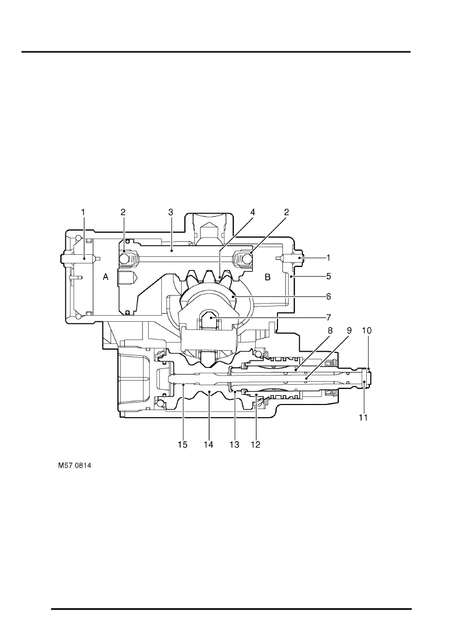
Cross section through steering box
1 Relief valve stop 2 off
2 Relief valve 2 off
3 Piston
4 Rack
5 Housing
6 Output shaft
7 Roller
8 Valve rotor
9 Torsion bar
10 Input shaft
11 Pin
12 Valve sleeve
13 Course spline
14 Worm gear
15 Spline (worm gear to torsion bar)