Discovery II

STEERING
DESCRIPTION AND OPERATION
57-11
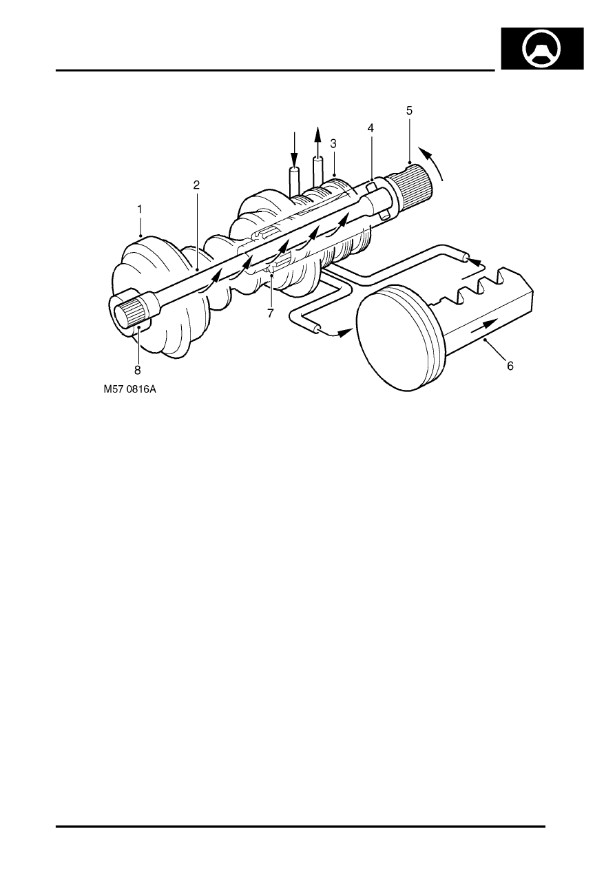
Rotary control valve in demand mode
1 Worm gear
2 Torsion bar
3 Valve sleeve
4 Pin
5 Input shaft and valve rotor
6 Piston/rack
7 Coarse spline
8 Spline (torque shaft to worm gear)
When the steering wheel and input shaft is turned steering resistance transmitted to the worm causes the torsion bar
to be wound up and the valve ports in the valve rotor and valve sleeve to be aligned for a right or left turn. The
alignment of the valve ports directs fluid pressure 'A' from the PAS pump to one side of the piston/rack . The other
side of the piston/rack is now connected to return 'B' (due the valves port alignment) and displaced fluid returns to the
reservoir. The pressure difference in the cylinder on each side of the piston gives the power assistance to move the
rack and so turn the steering.
The greater the resistance of the road wheels to the steering rotary movement, the greater torque acting on the torsion
bar and input shaft causing greater changes of alignment of the ports in the valve. As the change of alignment
becomes greater, the fluid pressure passing to the applicable side of the piston/rack increases.
Only when the steering wheel stops turning and the torsion bar has unwound, will the valve rotor return to the neutral
position. In the neutral position the fluid circulates through the ports in the valve rotor and valve sleeve and back to
the reservoir where it is cooled.
