
300Tdi Discovery
26
COOLING SYSTEM
4
DESCRIPTION AND OPERATION
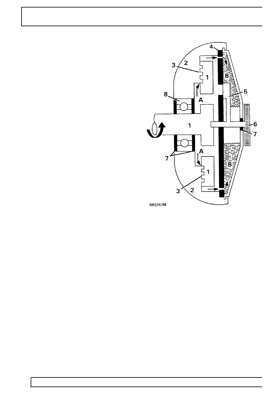
Operation
The viscous unit consists of two principal components:
An inner member 1 which is secured to water pump
spindle and is driven by the fan belt.
An outer member 2 which has the fan blades
attached, houses the working parts and is driven
through the medium of the viscous fluid.
The inner and outer members have interlocking
annular grooves machined in each, with a small
running clearance 3 to allow the silicone fluid to
circulate through the valve plate 4.
The unit also contains a valve 5 which is controlled by
an external bi-metal thermostat 6.
Starting engine from cold
During the time the engine is at rest the silicone fluid
drains down, half filling chambers A and B. Thus when
the engine is first started sufficient fluid is present in
chamber A to provide a positive drive between the
members, as is evident by the initial noise of the fan.
However within a very short period of time, after
starting the engine, the fan speed and noise will
decline indicating that the fluid is being centrifuged
into chamber B (as seen in RR3757M) causing the
drive to slip.
Viscous unit slipping (Engine at normal running
temperature)
1. Inner member (drive in fast)
2. Outer member (drive out slow)
3. Running clearance
4. Valve plate
5. Valve (closed)
6. Bi-metal
7. Fluid seals
8. Ball race
A. Fluid chamber
B. Fluid chamber
If the engine speed is increased the degree of slip will
also increase to limit the maximum fan speed.