
300Tdi Discovery
ZF
13
REPAIR
KICKDOWN CABLE
Service repair no - 44.15.01
Remove
1. Site vehicle on a four post ramp [hoist].
2. Select neutral ’N’ gear lever.
3. Disconnect battery negative lead.
4. Disconnect kickdown cable at throttle linkage.
5. Release outer cable locknut.
6. Disconnect cable from mounting bracket.
7. Release cable from bracket attached to cylinder
head.
8. Feed cable through to underside of vehicle.
9. Raise vehicle on ramp [hoist].
10. Drain oil and refit plug with new seal.
11. Detach heat shield at front exhaust pipe to
manifold.
12. Disconnect electrics from Lambda sensors.
13. Remove catalytic converter assembly.
14. Remove chassis cross-member from under
gearbox.
15. Disconnect dipstick tube at oil sump. Loosen
securing bolt at bell housing and move dipstick
aside.
16. Remove clamps securing oil sump. Note their
locations for refit, and withdraw sump.
17. Pull kickdown inner cable to fully open valve
cam. Wedge cam in this position.
18. Release cable from cam by pushing inner cable
into outer casing and detaching cable nipple
from cam.
19. Using special tool LST112 compress cable tangs
and remove cable from gearbox.
20. If cable is to be refitted remove ’O’ ring seal and
clean cable assembly.
Refit
21. Fit new ’O’ ring seal to cable and lubricate seal.
22. Fit cable to gearbox casing ensuring it is
correctly seated.
23. Fit inner cable nipple to its location on cam.
NOTE: When a new cable is fitted, to help
locate nipple to cam, introduce a curve
into the cable. Do not bend or kink cable.
24. Remove wedge from cam and ensure nipple
remains engaged.
25. Feed free end of cable assembly into engine
compartment.
26. Refit oil pan using a new gasket.
27. Connect dipstick tube to oil sump and tighten
bolt at bell housing.
28. Refit chassis cross-member
29. Refit catalytic converter assembly
30. Connect electrics to Lambda sensors.
31. Connect heat shield front pipe to manifold.
32. Lower vehicle on ramp [hoist].
33. Fit cable to bracket at cylinder head.
34. Locate cable in mounting bracket, do not tighten
locknut.
35. Fit cable to throttle linkage.
36. Ensure throttle linkage is fully closed.
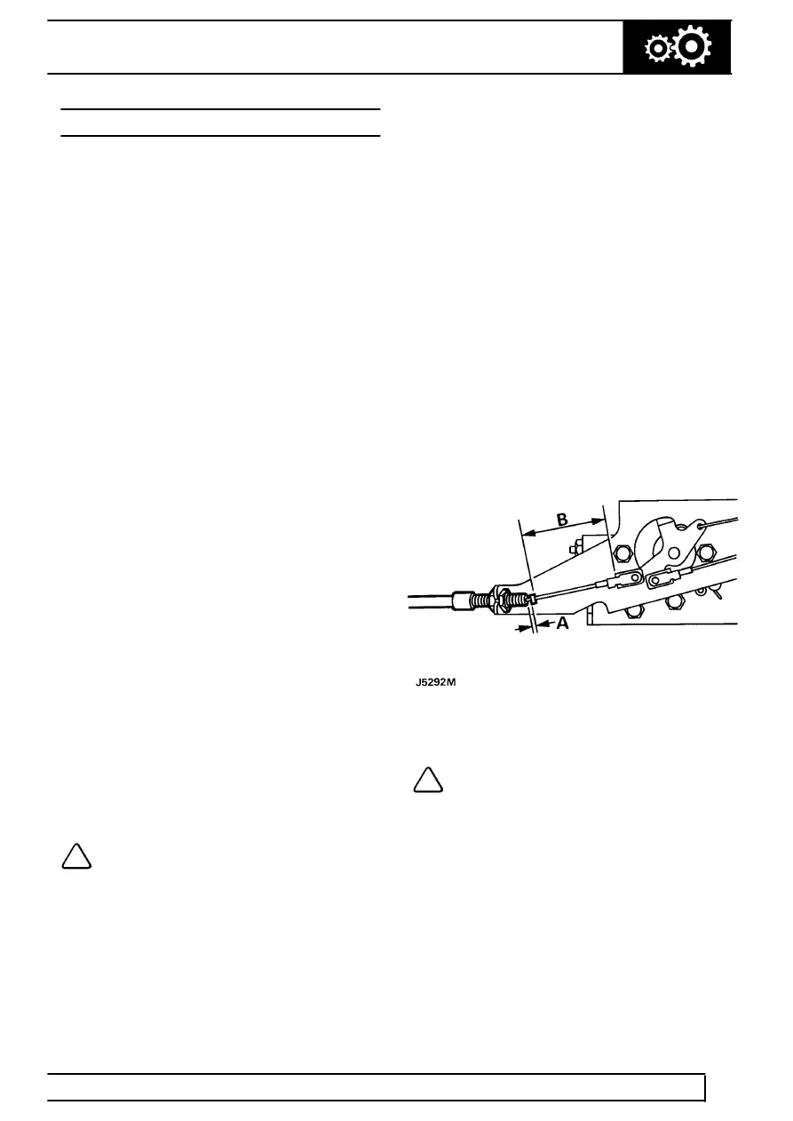
37. Adjust outer cable to achieve a gap of 0,25 to
1,25mm (dimension ’A’) between end of outer
cable and crimped collar on inner cable.
38. Tighten locknuts and recheck gap.
NOTE: If fitting a new cable, and collar on
inner cable is loose, measure distance ’B’
on old cable. Crimp collar on new cable to
this dimension.
39. Reconnect battery negative lead.
40. Refill gearbox oil using correct grade of oil.
See
LUBRICANTS, FLUIDS AND CAPACITIES,
Information, Recommended Lubricants and
Fluids