
300Tdi Discovery
STEERING
5
DESCRIPTION AND OPERATION
Rotary valve operation
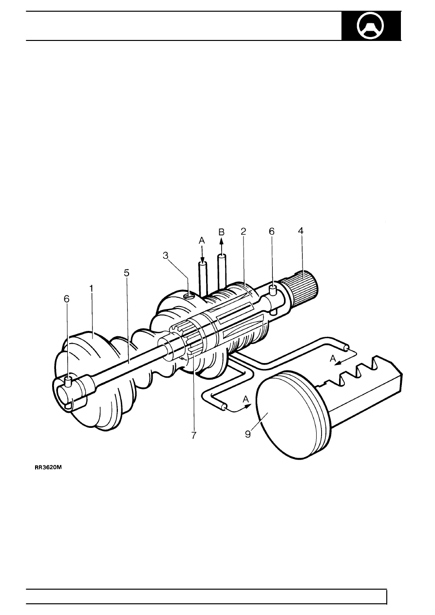
The rotary valve assembly seen in RR3620M
comprises the worm (1), the valve sleeve (2), the input
shaft (4) and the torsion bar (5).
The valve sleeve is retained inside the worm by the
trim screw (3), and incorporates valve ports in its inner
bore. The input shaft is attached to the steering wheel
via the steering shaft and steering column and
incorporates valve ports in its outer diameter to align
with those in the sleeve. The torsion bar which is
secured to the worm and input shaft with pins (6) at
each end (later models use one pin at input shaft
end), holds the valve ports in neutral alignment when
there is no demand for assistance.
No demand for assistance (Valve at neutral)
When there is no demand for assistance as seen in
RR3620M, the torsion bar holds the input shaft and
sleeve valve ports in neutral relationship to one
another, allowing equal pump pressure A to both
sides of the piston/rack (9). Any excess fluid flow from
the pump returns to the reservoir via B.
Rotary valve at neutral