
300Tdi Discovery
86
ELECTRICAL
12
REPAIR
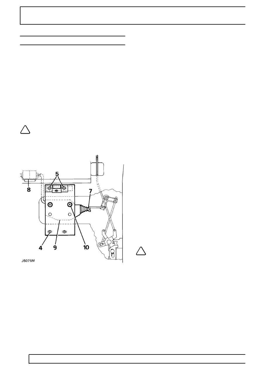
FRONT DOOR ACTUATOR UNIT
Service repair no - 86.26.08
Remove
1. Ensure that the window glass is in its fully closed
position.
2. Disconnect battery negative lead.
3. Remove the door pull, trim panel and plastic
vapour barrier.
See CHASSIS AND BODY,
Repair, Front Door Trim Panel
4. Remove the lower two screws and plain washers
securing the actuator mounting plate to the inner
door panel.
NOTE: The upper two actuator mounting
plate securing screws also secure one of
the door pull mounting brackets and
locate with a nut retainer strip fitted on the inside
face of the inner door panel.
5. Remove the upper two screws, the door pull
mounting bracket and retrieve the nut retaining
strip from inside the door.
6. Release the window lift motor leads from the
three clips at the front of the door to allow
sufficient slack in the harness for actuator
assembly removal.
7. Detach actuator assembly operating rod from the
actuator link on the door lock.
8. Withdraw the actuator assembly from the door
until the electrical cable is pulled out of its
channel sufficiently to expose the connector.
9. Detach the connector and remove the actuator
from the door.
10. The actuator unit may be changed by removing
the two rubber mounted screws that secure it to
the mounting plate.
Refit
11. Attach the actuator assembly connector to its
mating half on the door harness.
12. Engage the actuator assembly operating rod
with the hooked end of the actuator link.
13. Pull the door harness back into its channel from
the front end and secure the window lift motor
leads with the three clips.
14. Fit the actuator assembly to the inner door panel
and loosely secure with the two lower screws
and plain washers.
15. Position the nut retainer on the inside face of the
inner door panel, locate the door pull mounting
bracket and loosely secure with the two upper
screws.
16. Set the actuator mounting plate with the screws
in the centre of the slotted holes, then tighten the
screws sufficiently to retain the assembly.
17. Ensure that manual operation of the sill locking
control is not restricted by the operation of the
actuator operating rod and vice versa, resetting
the mounting plate as necessary.
18. Reconnect battery negative lead.
19. Check that electrical operation of the door lock
occurs when the sill locking control is moved
through half of its total movement. Reset the
mounting plate as necessary and fully tighten the
four screws.
NOTE: The above adjustment ensures that
the full tolerance on the switching
operation is utilised.