Freelander System Description and Operation

AUTOMATIC GEARBOX - JATCO
44-30
DESCRIPTION AND OPERATION
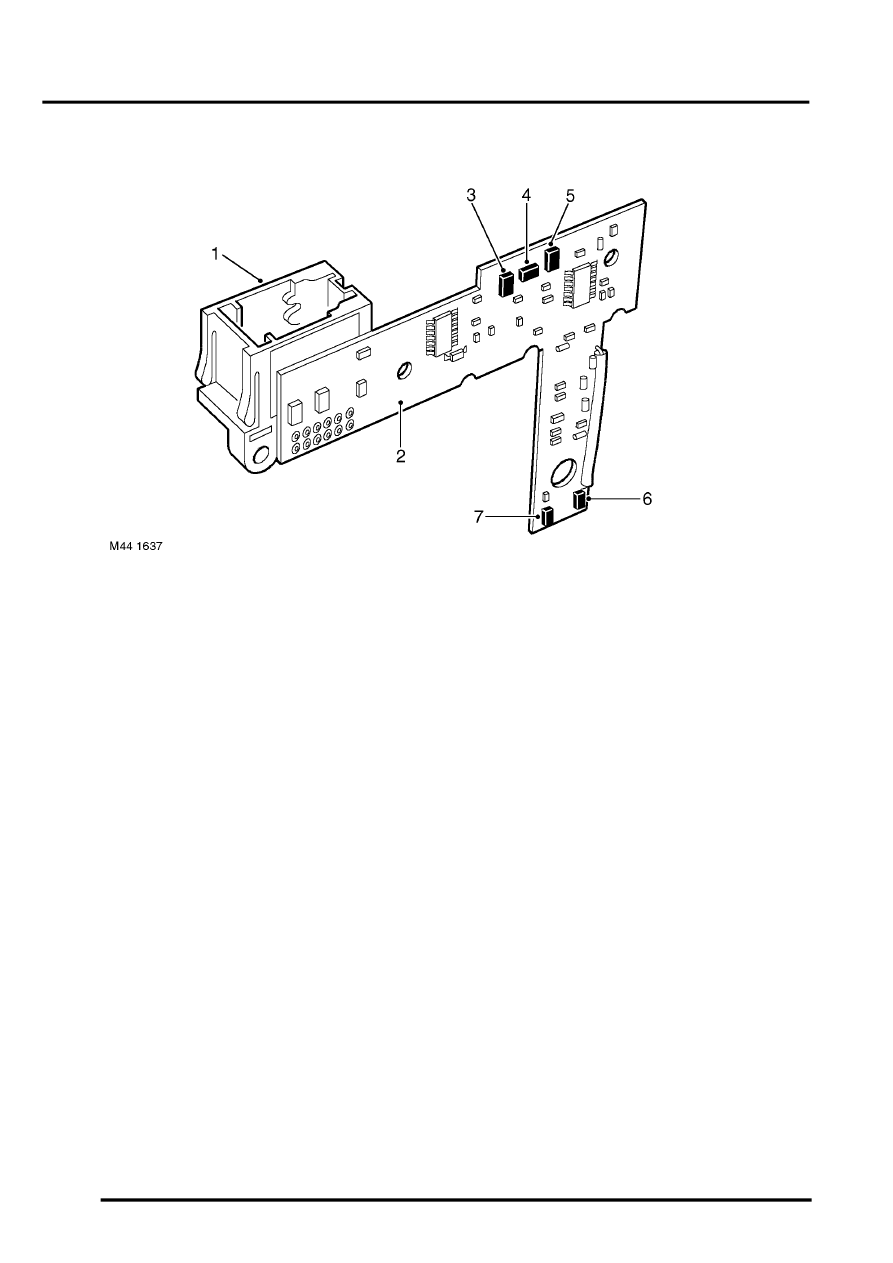
Sport/Manual Switch
1 Connector
2 PCB
3 '4' sensor
4 'D' sensor
5 'N' sensor
6 '+' (plus) sensor
7 '-' (minus) sensor
The sport/manual switch comprises a PCB and connector socket which is located to the left of the selector lever and
is an integral part of the selector lever assembly and cannot be serviced separately. The switch is connected to the
main harness by a twelve pin connector.
The sport/manual switch has five proximity sensors which correspond to the D, N, 4 and +/- positions. The selector
lever has two targets. An upper target is aligned with the DN4 sensors and the lower target is aligned with the +/-
sensors.
When the selector lever is in the D position, the D sensor is aligned with the target and the EAT ECU receives a signal
that D is selected. When the selector lever is moved to the S/M (sport) position, the target moves away from the
sensor. This is sensed by the ECU which then initiates sport mode.
The sensors in the N and 4 positions inform the ECU that D has been deselected, but not to the S/M position,
preventing the ECU from incorrectly initiating sport mode.
When the selector lever is moved to the S/M position, the target moves away from the D sensor. If the EAT ECU does
not receive a signal from either the 4 or N sensors, it determines that sport has been selected. The lower target is
positioned between the two sensors for +/- selection. If the selector lever is not moved to the +/- positions, the ECU
keeps the gearbox in sport mode. If the ECU senses a signal from either the + or - sensor, it initiates manual mode
and selects the manual gear selection requested. Manual mode will be maintained until the ECU senses a signal from
the D sensor.
