Freelander System Description and Operation

AUTOMATIC GEARBOX - JATCO
DESCRIPTION AND OPERATION
44-11
Power Flows
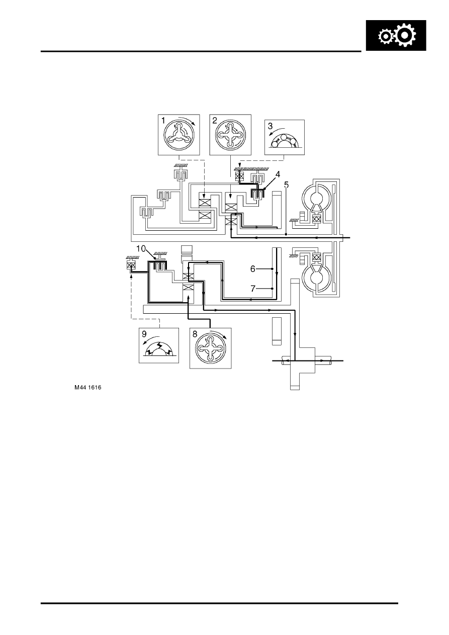
The following figures show the power flow in the gearbox for each forward gear and reverse.
1st Gear (D selected)
1 Front planetary gear
2 Rear planetary gear
3 Low one-way clutch
4 Low clutch
5 Input shaft
6 Output gear
7 Idler gear
8 Reduction planetary gear
9 Reduction one-way clutch
10 Reduction brake
On 1st gear selection, the low clutch and the reduction brake are engaged. During acceleration in 1st gear, the low
one-way clutch and the reduction clutch are locked. Power flows from the input shaft to the rear sun gear to rotate it
clockwise and the rear pinion gear rotates anti-clockwise. The rear internal gear tries to rotate clockwise. However,
because the internal gear is connected to the low one-way clutch through the low clutch, the rear internal gear cannot
rotate. Consequently, the rear planetary carrier and the output gear rotate clockwise. The output gear rotation is
transmitted to the reduction internal gear by the idler gear. The reduction brake locks the reduction sun gear. The
reduction gear rotates clockwise and makes the reduction planetary carrier rotate clockwise simultaneously. The
reduction gear rotates clockwise and transmits the power to the final drive and out to the road wheels.
