Freelander System Description and Operation

BRAKES
DESCRIPTION AND OPERATION
70-1
BRAKES
DESCRIPTION AND OPERATION
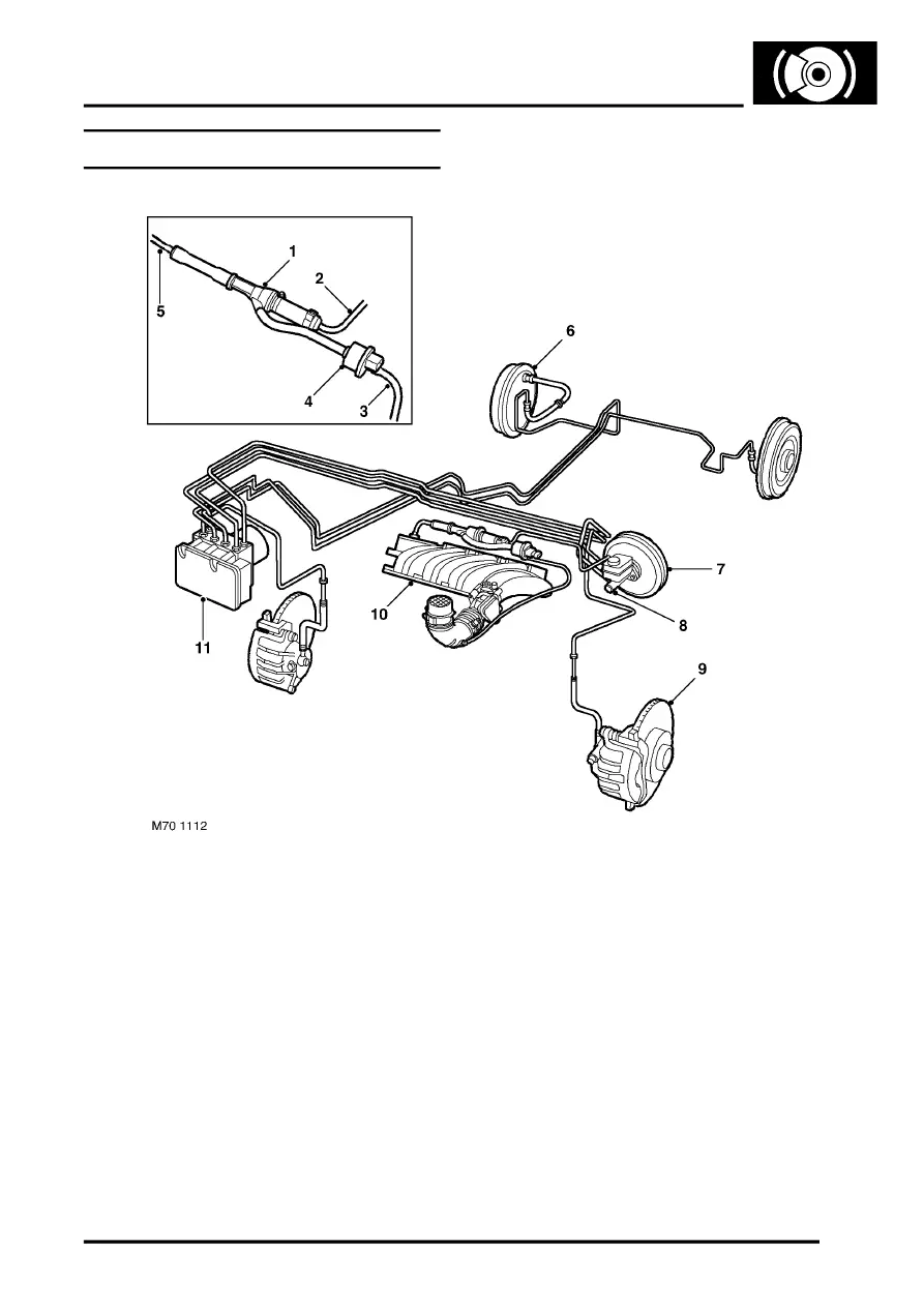
Brake System Layout (KV6)
LHD shown, RHD similar
NOTE: The vacuum enhancer solenoid valve (item 4) is applicable to all models except NAS KV6 from 2003 model
year onwards.
1 Vacuum enhancer venturi valve
2 Vacuum pipe from brake servo
3 Air feed pipe from intake duct
4 Vacuum enhancer solenoid valve
5 Vacuum pipe from inlet manifold
6 Rear brake
7 Brake servo assembly
8 Master cylinder assembly
9 Front brake
10 Engine inlet manifold
11 ABS modulator/ECU
