
Freelander System Description and Operation
DRIVESHAFTS
47-6
DESCRIPTION AND OPERATION
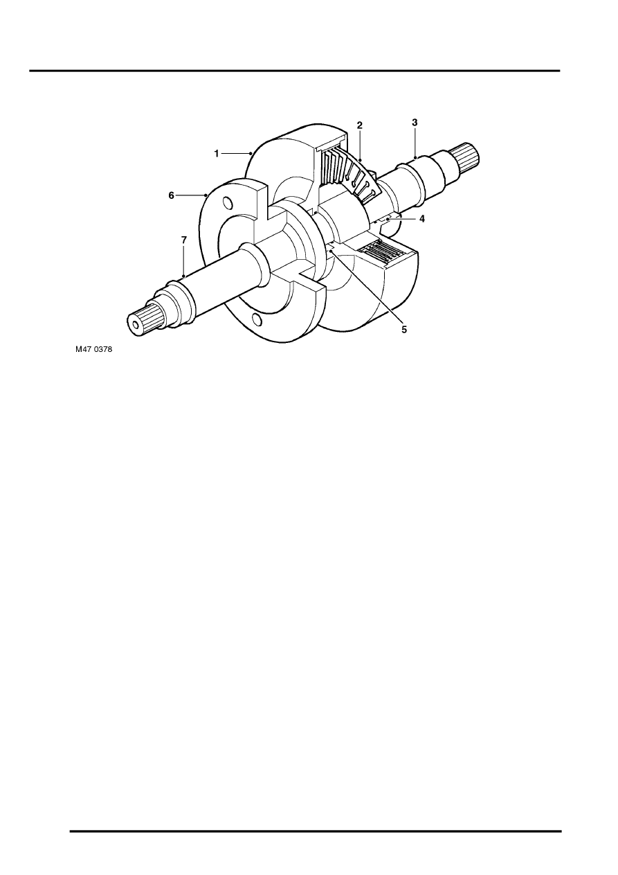
Section Through VCU
1 Cylinder
2 Slotted discs
3 Input shaft
4 Roller bearing
5 Ball bearing
6 Torsional damper flange (K1.8 models only)
7 Output shaft
The rear wheels are 0.8% under driven, so in most conditions the vehicle is effectively front wheel drive, with the rear
wheels turning the rear propeller shaft slightly faster than the IRD drives the front propeller shaft. Since the speed
differential is low, the increase in viscosity of the silicon jelly is marginal and there is little resistance to relative rotation
of the slotted discs.
When there is a significant speed differential between the front and rear propeller shafts , e.g. the front wheels lose
traction or traversing rough terrain, the viscosity and resistance to rotation of the silicon jelly increases to a level that
slows or stops relative rotation of the slotted discs. With the front and rear propeller shafts locked together, drive is
thus transferred from the IRD to the rear wheels.
Propeller Shaft Bearings
The two propeller shaft bearings are identical, and each consist of a roller bearing race mounted into a centre bearing
housing. The bearing is sealed-for-life and is a press fit on the input/output shaft of the VCU. Bearing covers and
flingers prevent the ingress of moisture.
Rear Propeller Shaft
The rear propeller shaft consists of a thin walled tube with a conventional universal joint welded to each end. The rear
universal joint is bolted to the input flange of the final drive unit. The front universal joint is splined to the output shaft
of the viscous coupling unit and secured by a bolt which is locked by a tabwasher and a 'U' washer. Both universal
joints incorporate serviceable, sealed needle bearings.