
Freelander System Description and Operation
EMISSION CONTROL - K SERIES KV6
DESCRIPTION AND OPERATION
17-3-7
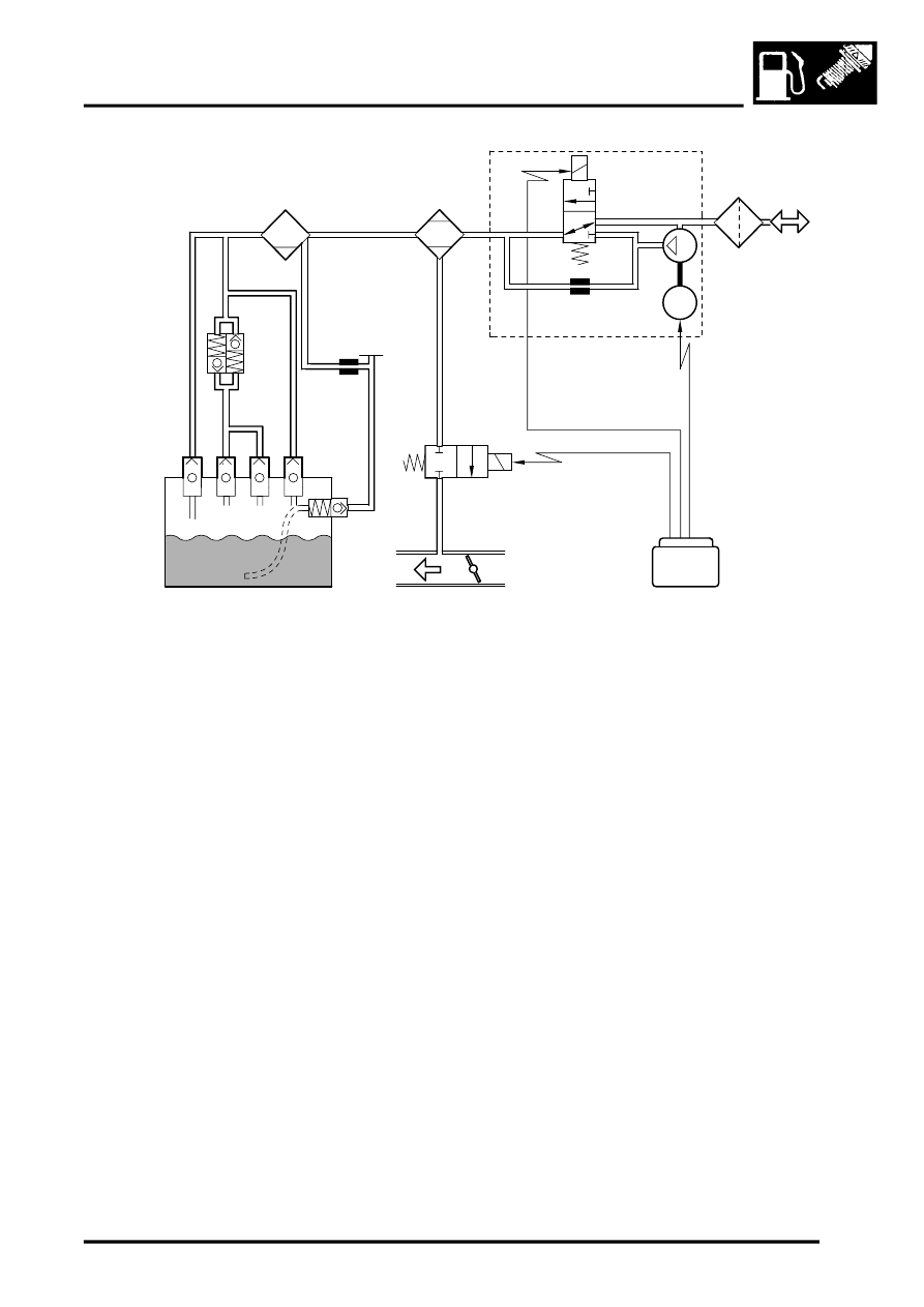
EVAP System Schematic – Vehicles from 2002.5 Model Year
1 Vapour separator
2 EVAP canister
3 DMTL
4 Change-over valve
5 0.5 mm (0.020 in) reference orifice
6 Air pump and motor
7 Air filter
8 ECM
9 Throttle body
10 Purge valve
11 Flap valve
12 Fuel tank
13 Roll over valve
14 ORVR valve
15 Two-way valve
16 Restrictor
17 Fuel filler cap
18 Filler tube
19 Fabric sleeve
Two-way Valve
The two-way valve limits the pressure and depression in the fuel tank and, during refuelling, induces automatic cut-
off in the refuelling nozzle when the fuel in the tank reaches the full level. The two-way valve is installed in the vent
pipe from the tank, next to the fuel pump assembly.
The two-way valve is a normally closed valve that opens, to release pressure from the fuel tank, at 18 to 50 mbar (0.26
and 0.73 lbf/in
2
). Air is allowed to flow back into the fuel tank, as the pressure in the tank decreases, through a non
return valve within the body of the two-way valve. The nominal opening pressure of the non return valve is 1 mbar
(0.015 lbf/in
2
).
During refuelling, if the fuel in the tank reaches the full level outward venting becomes restricted, which creates a back
pressure in the filler tube and automatically closes the refuelling nozzle. The restriction is caused by the fuel closing
the ORVR valve.
18
15
14
13
13
13
4
M17 0362
1
2
3
16
17
12
11
10
9
8
7
6
1
5
M
19