
Ignition Coils in Freelander: Up to 2003 Model Year
ENGINE MANAGEMENT SYSTEM - SIEMENS
DESCRIPTION AND OPERATION 18-4-27
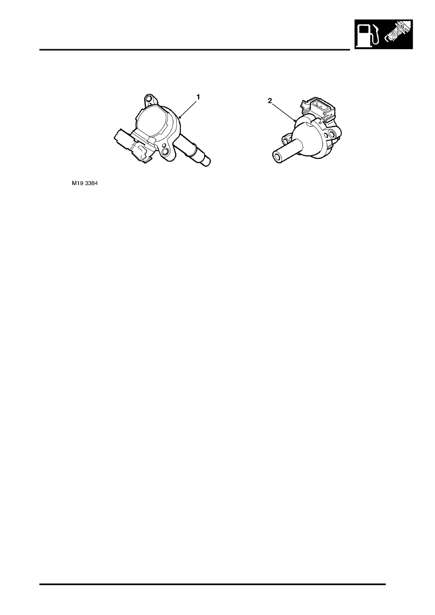
Ignition Coils – Up to 2003 Model Year
1 RH bank ignition coil
2 LH bank ignition coil
The ECM uses a separate ignition coil for each spark plug. The ignition coils for the LH bank spark plugs are
positioned on the forward tracts of the inlet manifold and connected to the spark plugs with High Tension (HT) leads.
The ignition coils for the RH bank spark plugs are of the plug top design, secured to the camshaft cover with 2 screws.
Each ignition coil has 3 connections in addition to the spark plug connection; an ignition feed from the main relay, an
earth wire for the secondary winding and a primary winding negative (switch) terminal. The switch terminal of each
ignition coil is connected to a separate pin on the ECM to allow independent switching. The ignition coils are charged
whenever the ECM supplies an earth path to the primary winding negative terminal. The duration of the charge time
is held relatively constant by the ECM for all engine speeds. Consequently, the dwell period increases with engine
speed. This type of system, referred to as Constant Energy, allows the use of low impedance coils with faster charge
times and higher outputs.
The ECM calculates the dwell period using inputs from the following:
l
Battery voltage (main relay).
l
CKP sensor.
l
Ignition coil primary current (internal ECM connection).
The spark is produced when the ECM breaks the primary winding circuit. This causes the magnetic flux around the
primary winding to collapse, inducing HT energy in the secondary coil, which can only pass to earth by bridging the
air gap of the spark plug.
Ignition related faults are monitored indirectly by the misfire detection function.