Freelander System Description and Operation

RESTRAINT SYSTEMS
75-10
DESCRIPTION AND OPERATION
SRS Warning Lamp
The SRS warning lamp provides system status information for the driver. The lamp consists of a non serviceable LED
behind a red SRS graphic, which is located below the speedometer in the instrument pack.
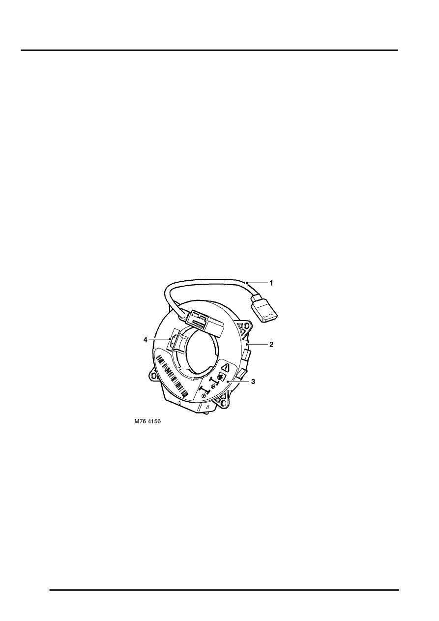
Rotary Coupler
The rotary coupler is installed on the steering column to provide the interface between the fixed wiring harness and
the moveable driver's airbag module. In addition to the wiring for the driver's airbag module, the rotary coupler also
provides the interface for the following switches which, depending on equipment level, can also be incorporated into
the steering wheel:
l
Horn switches.
l
ICE system control switches.
l
Cruise control system switches.
A rotating link harness is encapsulated into a plastic cassette comprising outer and inner housings with integral
connectors. Screws attach the outer housing to the steering column switch assembly and the inner housing is keyed
to the steering wheel by its connector. The inner housing can turn a maximum of five revolutions in relation to the outer
housing. For maintenance purposes the inner housing incorporates a position indicator wheel; a white segment is
visible on the wheel when the rotary coupler is centralised. To prevent breaking the rotating link harness, both the
steering and the rotary coupler must be centralised when removing and installing the steering wheel.
A new rotary coupler has a blue locking tab which ensures the unit is locked at its factory centred position. The peg
should remain intact until just before steering wheel fitment.
Rotary Coupler Components
1 Fly lead (to airbag module)
2 Outer housing
3 Inner housing
4 Position indicator wheel
