Freelander System Description and Operation

STEERING
57-14
DESCRIPTION AND OPERATION
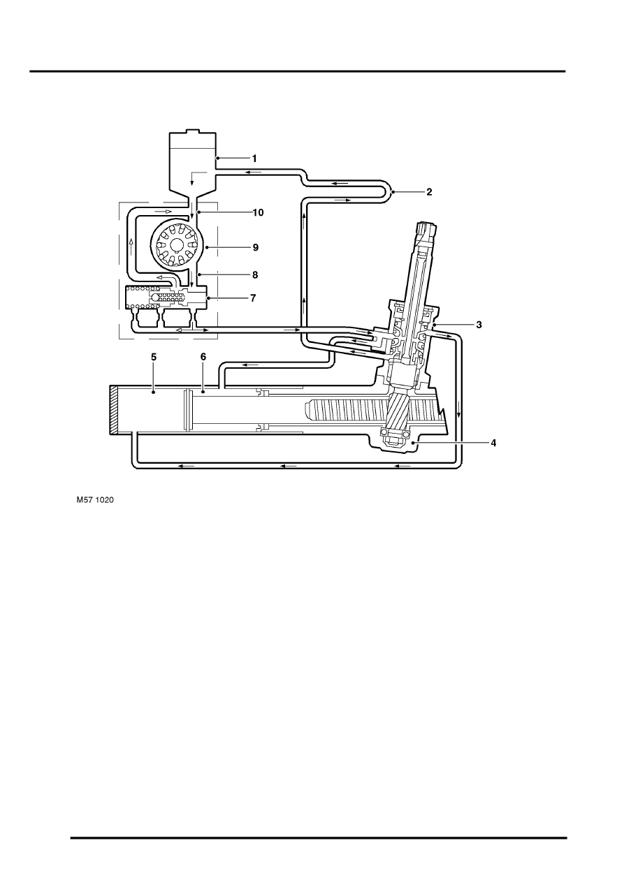
Hydraulic Circuit Operation
1 Reservoir
2 Fluid cooler
3 Valve unit
4 Steering rack and pinion gear
5 Full area pressure chamber
6 Annulus pressure chamber
7 Flow control/relief valve
8 Discharge port
9 PAS pump
10 Low pressure suction line
When the engine is started, the PAS pump draws fluid from the reservoir down the low pressure suction line. The fluid
passes through the PAS pump and emerges as pressurised fluid at the discharge port. The attenuated high pressure
hose transports the pressurised fluid to the steering gear valve unit.
If no steering effort is applied, there is minimal restriction within the system and the supply pressure from the pump is
low. Minimal pressure is applied, via the valve unit, to each side of the piston in the hydraulic cylinder and the full flow
from the PAS pump returns to the reservoir via the fluid cooler.
If steering effort is applied in either direction, the return flow of fluid to the reservoir is restricted, causing the supply
pressure from the PAS pump to increase. The pressurised fluid is directed to the hydraulic cylinder, via the valve unit,
providing power assistance to reduce the steering effort required. The fluid displaced by the movement of the piston
in the cylinder is returned through the valve unit to the reservoir via the fluid cooler.
The fluid cooler reduces the fluid temperature which prolongs the life of the hoses and seals in the system.
