Freelander System Description and Operation

WIPERS AND WASHERS
DESCRIPTION AND OPERATION
84-5
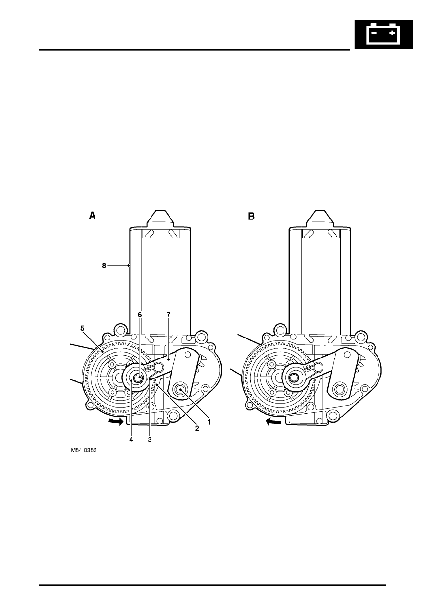
When the motor changes direction, the eccentric cam is rotated through 180
°
which effectively lengthens the linear
movement of the connecting link. This causes the wiper arm to sweep across the screen to its park position. The
longer linear movement of the connecting link, causes the wiper arm to rotate further than during normal wiping,
parking the wiper arm and blade off screen. A second slip ring operated microswitch, on the underside of the gear
wheel, signals the CCU that the wiper arm has reached the off screen position and the CCU removes the supply to
the rear screen wiper motor.
The wiper arm is located on the splined shaft from the motor and secured with a nut. The wiper arm attachment to the
splined shaft has a pivot to which the remainder of the arm is attached. The two parts of the arm are connected by a
spring which controls the pressure of the blade on the screen to a predetermined amount.
The wiper blade is pushed onto the wiper arm which has a clip-on feature that allows the blade to pivot. The wiper
blade comprises a lever, two yokes and a plastic strip. The rubber wiper is fitted to the plastic strip and held in the
yokes. The lever, yokes and plastic strip ensure that pressure applied by the arm spring is distributed evenly along
the length of the blade.
Rear Screen Wiper Operating Principle
A = Motor operating (forward operation - wiper at bottom of screen)
B = Park position (reverse operation - off-screen parked)
1 Splined shaft
2 Motor worm drive
3 Coil spring
4 Cam
5 Gear wheel
6 Spigot
7 Link
8 Motor
