
Water ingress into vehicle
- Make
- Land Rover
- Model
- Freelander Technical Bulletins
- Section
- Water ingress into vehicle › Water ingress into vehicle
WATER INGRESS INTO VEHICLE
- Model
- Freelander
- Affected vehicles
- All vehicles
- Date
- 2001-10-17
- Reference
- Bulletin 0076, CDS ref L8664bu
Bulletin text
Freelander
AFFECTED RANGE:
All vehicles
PROBLEM:
WATER INGRESS INTO VEHICLE
ACTION:
Upon customer complaint of water ingress into the vehicle, refer to the following procedures to identify sources of ingress and the required rectification.
PARTS INFORMATION:
Refer to individual repair processes for part numbers and repair materials.
WARRANTY CLAIMS: Select Complaint Codes and only claim against SRO’s from the tables below. Times claimed should reflect the work carried out and the job card should be endorsed with the repair procedure reference. For each Complaint Code used, a separate claim line will be required. REAR OF VEHICLE
Procedure Complaint
SRO
Code 1 9R0N 76.11.89/33
2 9L4N 76.11.89/49
3 8C6N 76.34.28 4 8G2N 76.31.25/01
5 & 6 9H1N 76.11.89/50
7 9U9N 76.11.89/51
9L8N 8 & 9 76.11.89/52 9L2N 10 9J4N 76.11.89/53 11 8T1N 76.11.89/54
Bulletin N o : 0076 L8664bu 1 17.10.01
Time Notes Allowance 0.70Hrs Seal both sides - claim only once 0.80Hrs if sealing front and rear 0.60Hrs 0.30Hrs Carry out both procedures - claim 0.40Hrs only once 0.80Hrs 3 door 1.0Hrs 5 door 3.1Hrs 3 door 3.2Hrs 5 door 0.30Hrs 0.30Hrs
FRONT OF VEHICLE
Procedure Complaint
SRO
Code 76.11.89/49
1 9L4N
76.11.30 77.90.89/26 2 9H6N 77.90.89/27 See procedure 77.90.89/28 3-6
7 9L5N 77.90.89/30
8 9H5N 77.90.89/33 9 9D4N 77.90.89/31 77.90.89/32 10 7Z4G 77.90.89/29
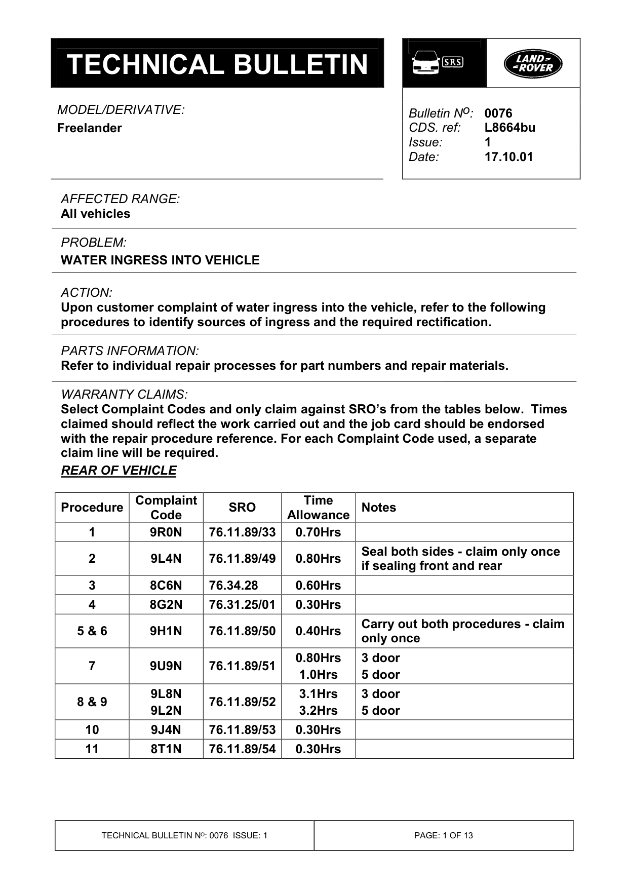
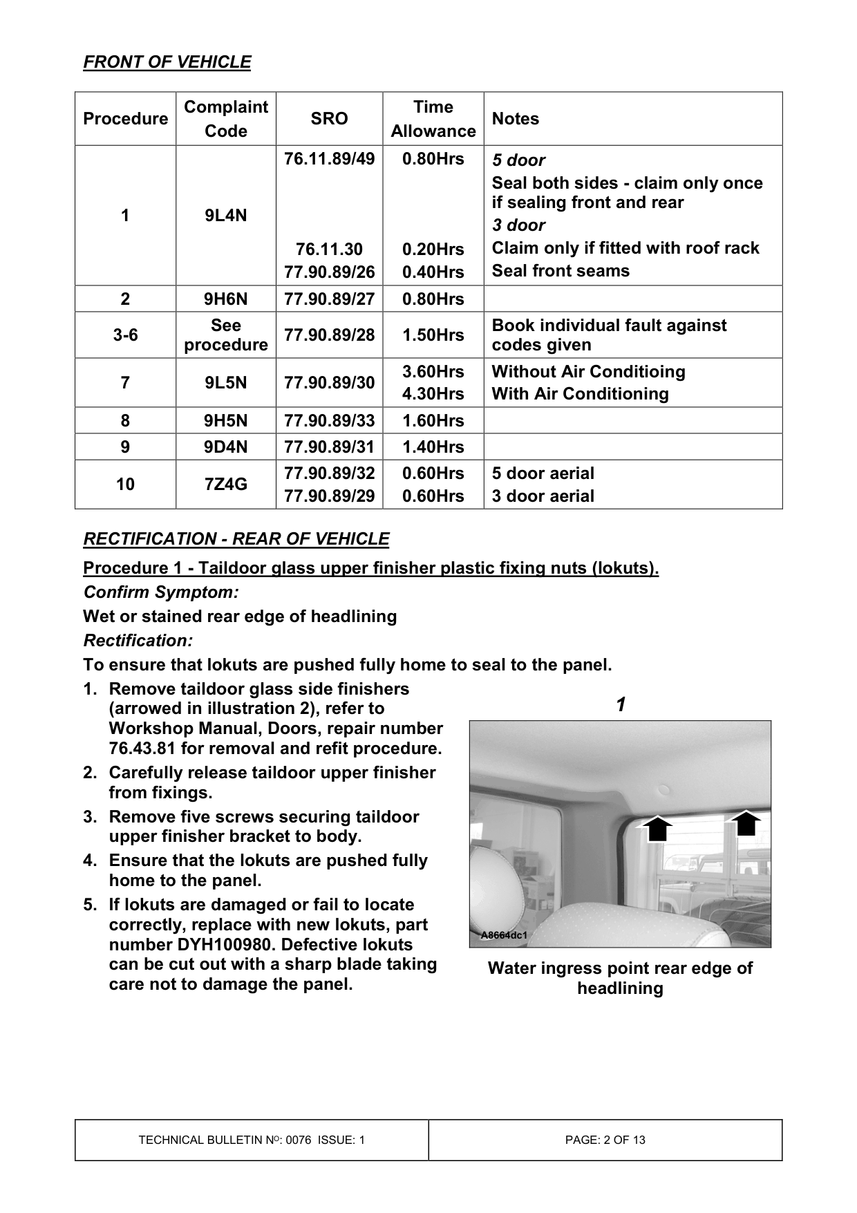
RECTIFICATION - REAR OF VEHICLE Procedure 1 - Taildoor glass upper finisher plastic fixing nuts (lokuts). Confirm Symptom: Wet or stained rear edge of headlining Rectification: To ensure that lokuts are pushed fully home to seal to the panel. 1. Remove taildoor glass side finishers (arrowed in illustration 2), refer to Workshop Manual, Doors, repair number 76.43.81 for removal and refit procedure. 2. Carefully release taildoor upper finisher from fixings. 3. Remove five screws securing taildoor upper finisher bracket to body. 4. Ensure that the lokuts are pushed fully home to the panel. 5. If lokuts are damaged or fail to locate correctly, replace with new lokuts, part number DYH100980. Defective lokuts can be cut out with a sharp blade taking care not to damage the panel.
Time Notes Allowance 0.80Hrs 5 door Seal both sides - claim only once if sealing front and rear 3 door Claim only if fitted with roof rack 0.20Hrs Seal front seams 0.40Hrs 0.80Hrs Book individual fault against 1.50Hrs codes given 3.60Hrs Without Air Conditioing 4.30Hrs With Air Conditioning 1.60Hrs 1.40Hrs 0.60Hrs 5 door aerial 0.60Hrs 3 door aerial
1
A8664dc1
Water ingress point rear edge of headlining
6. When satisfied that the lokuts are secure, apply water proof tape over them. 7. Fit the taildoor upper finisher and glass side finishers. When the finishers are refitted the securing screws will penetrate the tape. 8. Apply water to the suspected entry area to ensure leak has been cured.
PARTS INFORMATION:
DYH100980 - Lokut (as required) Water proof tape - Locally sourced
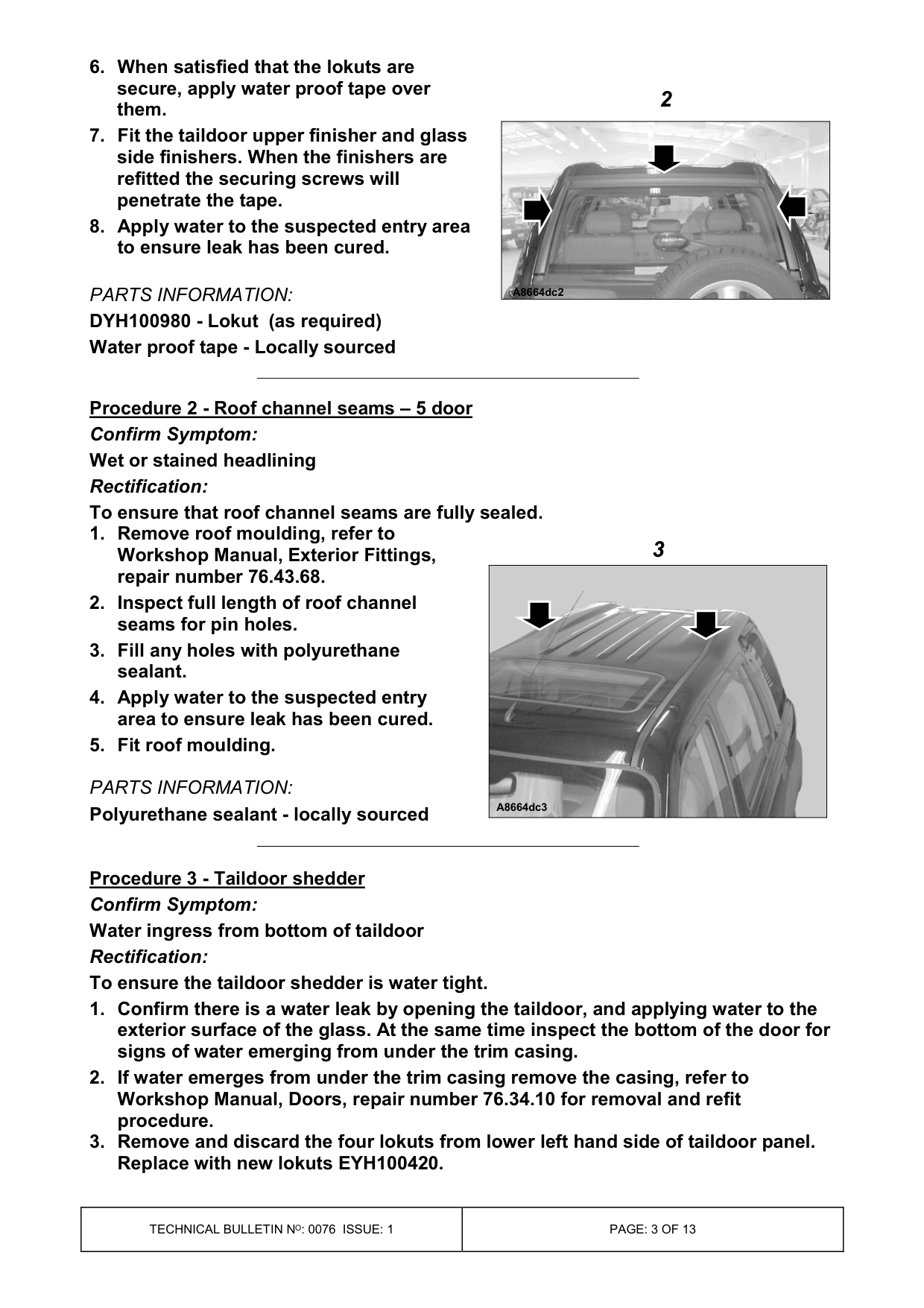
Procedure 2 - Roof channel seams - 5 door Confirm Symptom: Wet or stained headlining Rectification: To ensure that roof channel seams are fully sealed. 1. Remove roof moulding, refer to Workshop Manual, Exterior Fittings, repair number 76.43.68. 2. Inspect full length of roof channel seams for pin holes. 3. Fill any holes with polyurethane sealant. 4. Apply water to the suspected entry area to ensure leak has been cured. 5. Fit roof moulding.
PARTS INFORMATION:
Polyurethane sealant - locally sourced
Procedure 3 - Taildoor shedder Confirm Symptom: Water ingress from bottom of taildoor Rectification: To ensure the taildoor shedder is water tight. 1. Confirm there is a water leak by opening the taildoor, and applying water to the exterior surface of the glass. At the same time inspect the bottom of the door for signs of water emerging from under the trim casing. 2. If water emerges from under the trim casing remove the casing, refer to Workshop Manual, Doors, repair number 76.34.10 for removal and refit procedure. 3. Remove and discard the four lokuts from lower left hand side of taildoor panel. Replace with new lokuts EYH100420.
2
A8664dc2
3
A8664dc3
4. Inspect shedder for damage and for gaps in sealant between sheet and door. If damaged, the shedder must be replaced, refer to Workshop Manual, Doors, repair number 76.34.25. 5. When fitting new shedder :• Shedder and surface of vehicle must be between18 to 30 ° C. • Ensure no creases are present and adhesive contact areas are pushed fully down onto clean surfaces. Use suitable roller to ensure plastic sheet is fully sealed to the door. 6. If gaps are found in sealant, repair using polyurethane sealant. 7. Refit trim casing.
PARTS INFORMATION:
EYH 100420 - Plastic fixing nut (Lokut) ELD 100670 - Water shedder large AWR 5166 - Water shedder small Polyurethane sealant - locally sourced
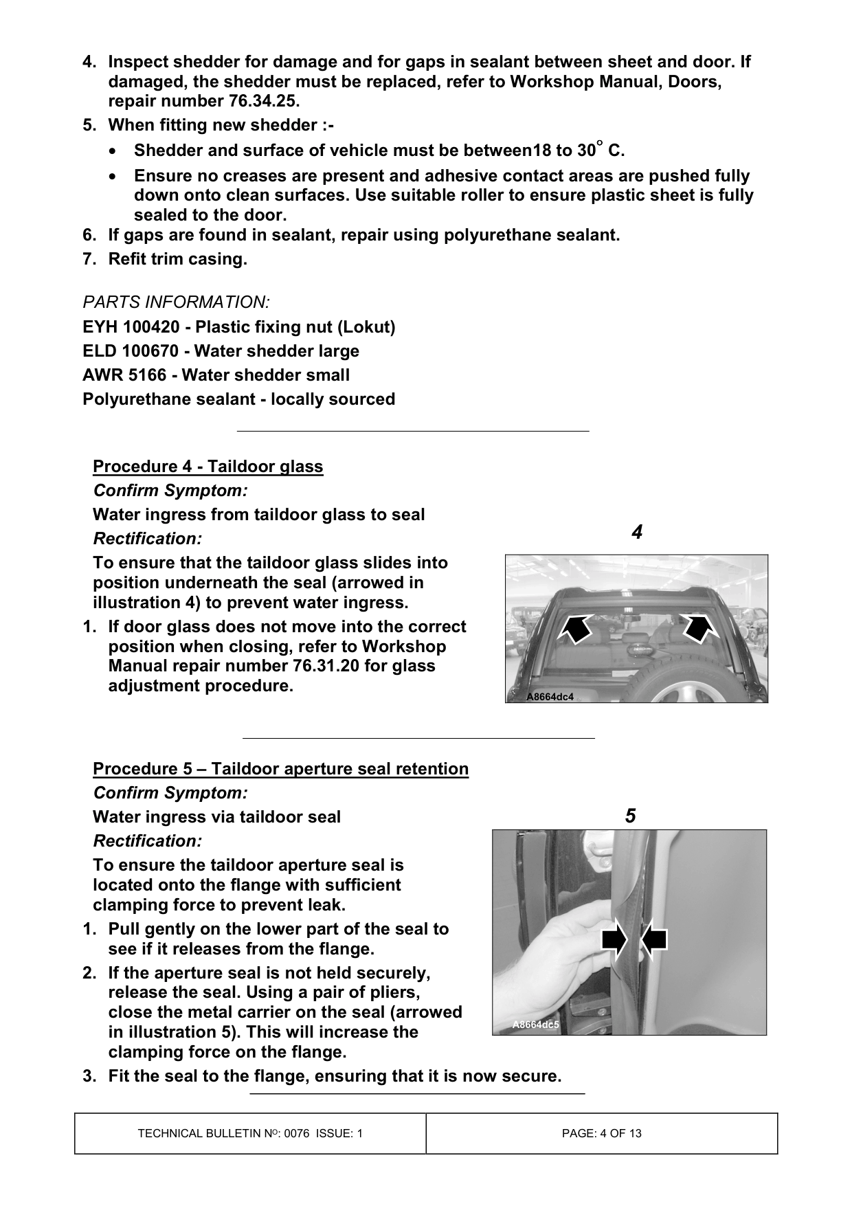
Procedure 4 - Taildoor glass Confirm Symptom: Water ingress from taildoor glass to seal Rectification: To ensure that the taildoor glass slides into position underneath the seal (arrowed in illustration 4) to prevent water ingress. 1. If door glass does not move into the correct position when closing, refer to Workshop Manual repair number 76.31.20 for glass adjustment procedure.
Procedure 5 - Taildoor aperture seal retention Confirm Symptom: Water ingress via taildoor seal Rectification: To ensure the taildoor aperture seal is located onto the flange with sufficient clamping force to prevent leak. 1. Pull gently on the lower part of the seal to see if it releases from the flange. 2. If the aperture seal is not held securely, release the seal. Using a pair of pliers, close the metal carrier on the seal (arrowed in illustration 5). This will increase the clamping force on the flange. 3. Fit the seal to the flange, ensuring that it is now secure.
4
A8664dc4
5
A8664dc5
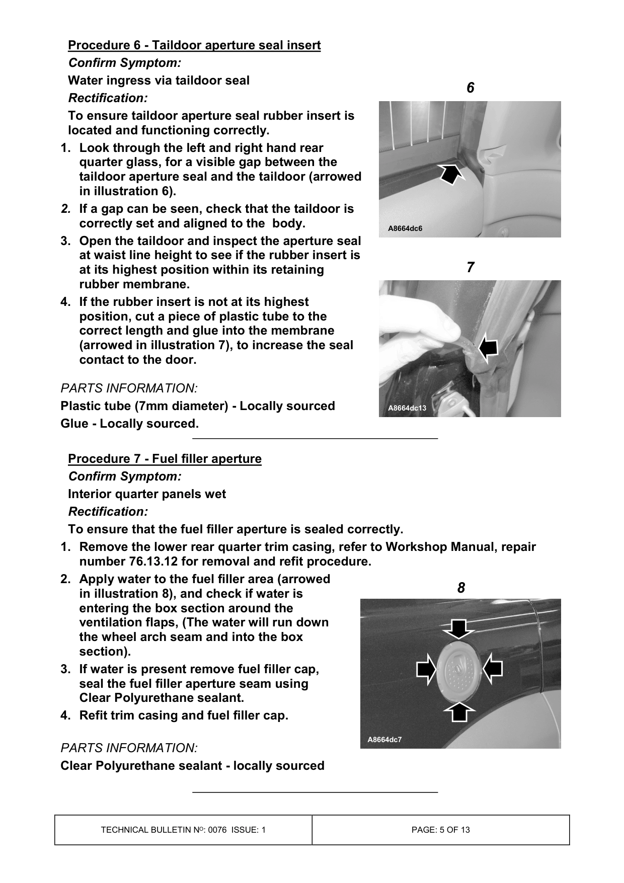
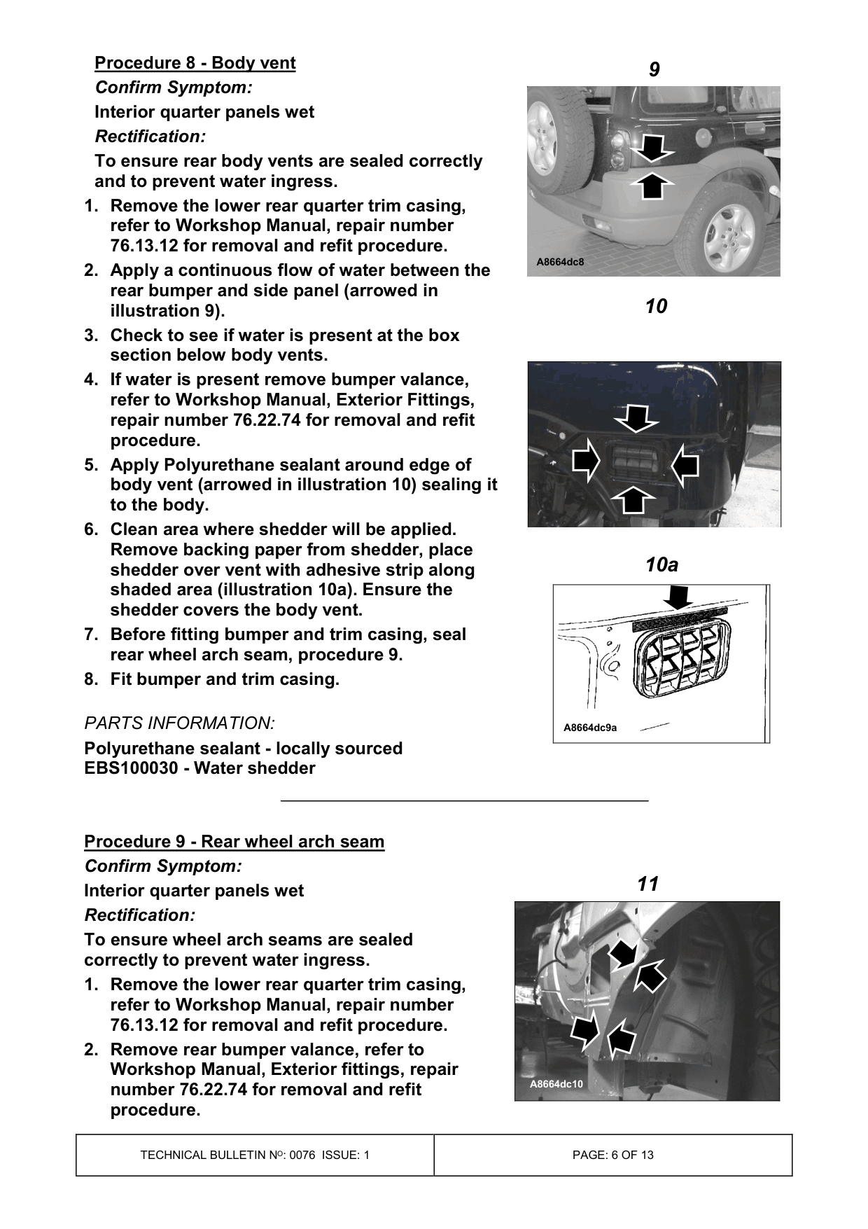
Procedure 6 - Taildoor aperture seal insert Confirm Symptom: Water ingress via taildoor seal Rectification: To ensure taildoor aperture seal rubber insert is located and functioning correctly. 1. Look through the left and right hand rear quarter glass, for a visible gap between the taildoor aperture seal and the taildoor (arrowed in illustration 6). 2. If a gap can be seen, check that the taildoor is correctly set and aligned to the body. 3. Open the taildoor and inspect the aperture seal at waist line height to see if the rubber insert is at its highest position within its retaining rubber membrane. 4. If the rubber insert is not at its highest position, cut a piece of plastic tube to the correct length and glue into the membrane (arrowed in illustration 7), to increase the seal contact to the door.
PARTS INFORMATION:
Plastic tube (7mm diameter) - Locally sourced Glue - Locally sourced.
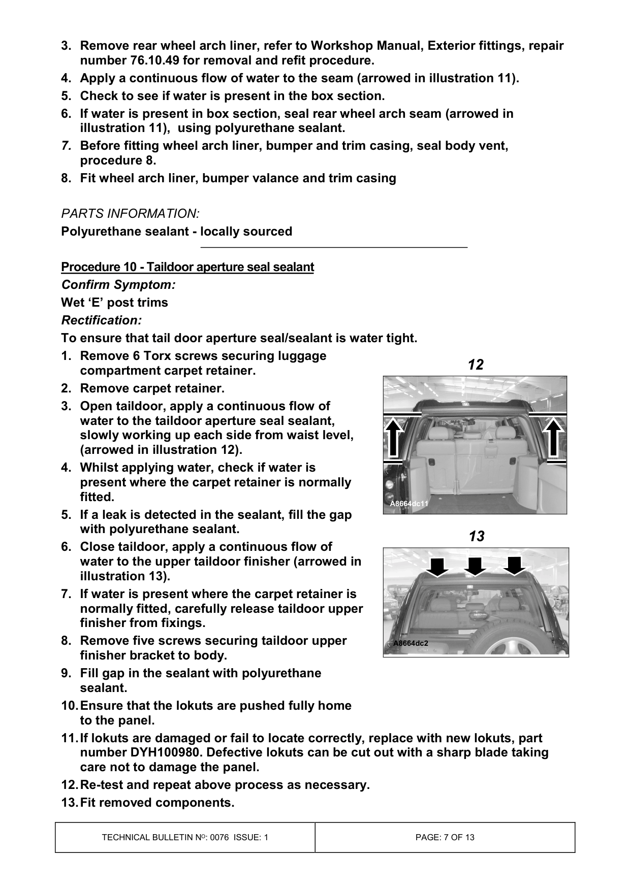
Procedure 7 - Fuel filler aperture Confirm Symptom: Interior quarter panels wet Rectification: To ensure that the fuel filler aperture is sealed correctly. 1. Remove the lower rear quarter trim casing, refer to Workshop Manual, repair number 76.13.12 for removal and refit procedure. 2. Apply water to the fuel filler area (arrowed in illustration 8), and check if water is entering the box section around the ventilation flaps, (The water will run down the wheel arch seam and into the box section). 3. If water is present remove fuel filler cap, seal the fuel filler aperture seam using Clear Polyurethane sealant. 4. Refit trim casing and fuel filler cap.
PARTS INFORMATION:
Clear Polyurethane sealant - locally sourced
6
A8664dc6
7
A8664dc13
8
A8664dc7
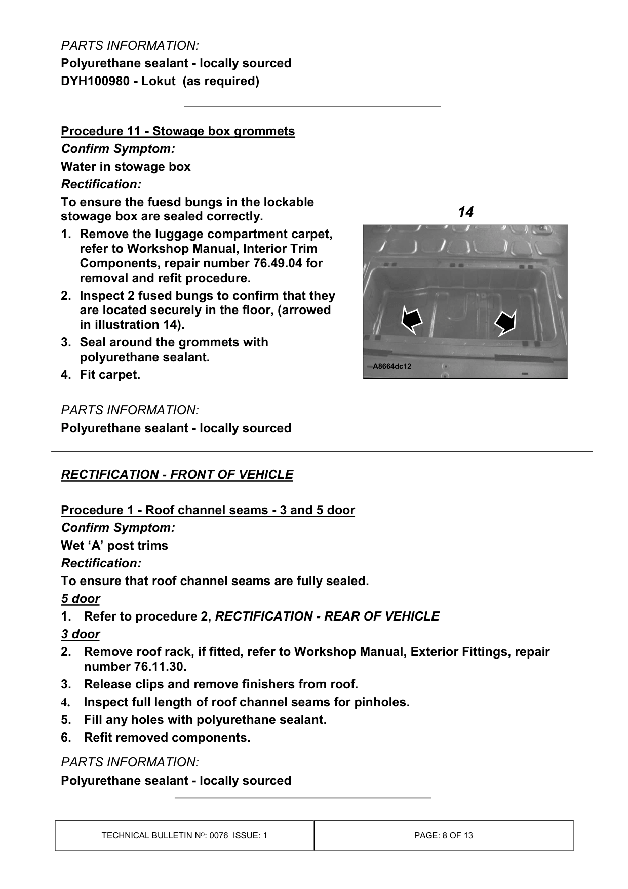
Procedure 8 - Body vent Confirm Symptom: Interior quarter panels wet Rectification: To ensure rear body vents are sealed correctly and to prevent water ingress. 1. Remove the lower rear quarter trim casing, refer to Workshop Manual, repair number 76.13.12 for removal and refit procedure. 2. Apply a continuous flow of water between the rear bumper and side panel (arrowed in illustration 9). 3. Check to see if water is present at the box section below body vents. 4. If water is present remove bumper valance, refer to Workshop Manual, Exterior Fittings, repair number 76.22.74 for removal and refit procedure. 5. Apply Polyurethane sealant around edge of body vent (arrowed in illustration 10) sealing it to the body. 6. Clean area where shedder will be applied. Remove backing paper from shedder, place shedder over vent with adhesive strip along shaded area (illustration 10a). Ensure the shedder covers the body vent. 7. Before fitting bumper and trim casing, seal rear wheel arch seam, procedure 9. 8. Fit bumper and trim casing.
PARTS INFORMATION:
Polyurethane sealant - locally sourced EBS100030 - Water shedder
Procedure 9 - Rear wheel arch seam Confirm Symptom: Interior quarter panels wet Rectification: To ensure wheel arch seams are sealed correctly to prevent water ingress. 1. Remove the lower rear quarter trim casing, refer to Workshop Manual, repair number 76.13.12 for removal and refit procedure. 2. Remove rear bumper valance, refer to Workshop Manual, Exterior fittings, repair number 76.22.74 for removal and refit procedure.
9
A8664dc8
10
10a
A8664dc9a
11
A8664dc10
3. Remove rear wheel arch liner, refer to Workshop Manual, Exterior fittings, repair number 76.10.49 for removal and refit procedure. 4. Apply a continuous flow of water to the seam (arrowed in illustration 11). 5. Check to see if water is present in the box section. 6. If water is present in box section, seal rear wheel arch seam (arrowed in illustration 11), using polyurethane sealant. 7. Before fitting wheel arch liner, bumper and trim casing, seal body vent, procedure 8. 8. Fit wheel arch liner, bumper valance and trim casing
PARTS INFORMATION:
Polyurethane sealant - locally sourced
Procedure 10 - Taildoor aperture seal sealant Confirm Symptom: Wet ‘E’ post trims Rectification: To ensure that tail door aperture seal/sealant is water tight. 1. Remove 6 Torx screws securing luggage compartment carpet retainer. 2. Remove carpet retainer. 3. Open taildoor, apply a continuous flow of water to the taildoor aperture seal sealant, slowly working up each side from waist level, (arrowed in illustration 12). 4. Whilst applying water, check if water is present where the carpet retainer is normally fitted. 5. If a leak is detected in the sealant, fill the gap with polyurethane sealant. 6. Close taildoor, apply a continuous flow of water to the upper taildoor finisher (arrowed in illustration 13). 7. If water is present where the carpet retainer is normally fitted, carefully release taildoor upper finisher from fixings. 8. Remove five screws securing taildoor upper finisher bracket to body. 9. Fill gap in the sealant with polyurethane sealant. 10. Ensure that the lokuts are pushed fully home to the panel. 11. If lokuts are damaged or fail to locate correctly, replace with new lokuts, part number DYH100980. Defective lokuts can be cut out with a sharp blade taking care not to damage the panel. 12. Re-test and repeat above process as necessary. 13. Fit removed components.
12
A8664dc11
13
A8664dc2
PARTS INFORMATION:
Polyurethane sealant - locally sourced DYH100980 - Lokut (as required)
Procedure 11 - Stowage box grommets Confirm Symptom: Water in stowage box Rectification: To ensure the fuesd bungs in the lockable stowage box are sealed correctly. 1. Remove the luggage compartment carpet, refer to Workshop Manual, Interior Trim Components, repair number 76.49.04 for removal and refit procedure. 2. Inspect 2 fused bungs to confirm that they are located securely in the floor, (arrowed in illustration 14). 3. Seal around the grommets with polyurethane sealant. 4. Fit carpet.
PARTS INFORMATION:
Polyurethane sealant - locally sourced
RECTIFICATION - FRONT OF VEHICLE
Procedure 1 - Roof channel seams - 3 and 5 door Confirm Symptom: Wet ‘A’ post trims Rectification: To ensure that roof channel seams are fully sealed. 5 door 1. Refer to procedure 2, RECTIFICATION - REAR OF VEHICLE 3 door 2. Remove roof rack, if fitted, refer to Workshop Manual, Exterior Fittings, repair number 76.11.30. 3. Release clips and remove finishers from roof. Inspect full length of roof channel seams for pinholes. 4. 5. Fill any holes with polyurethane sealant. 6. Refit removed components.
PARTS INFORMATION:
Polyurethane sealant - locally sourced
14
A8664dc12
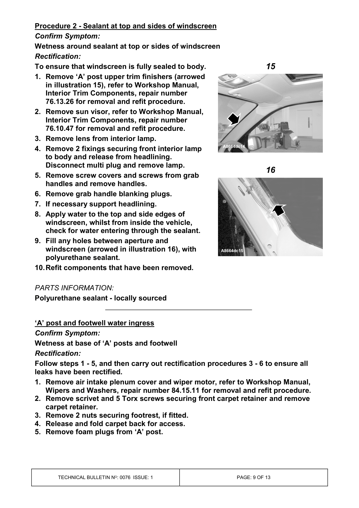
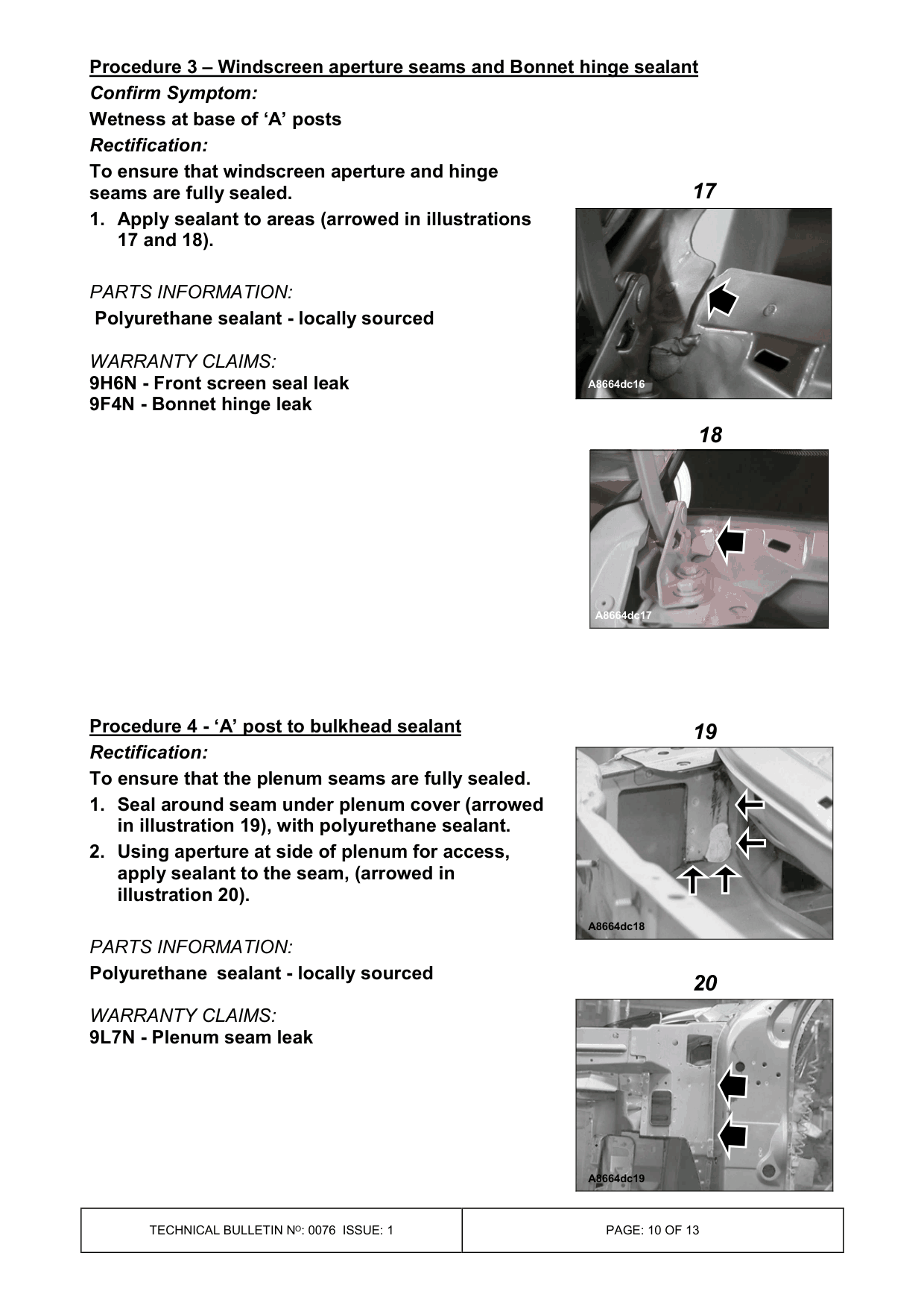
Procedure 2 - Sealant at top and sides of windscreen Confirm Symptom: Wetness around sealant at top or sides of windscreen Rectification: To ensure that windscreen is fully sealed to body. 1. Remove ‘A’ post upper trim finishers (arrowed in illustration 15), refer to Workshop Manual, Interior Trim Components, repair number 76.13.26 for removal and refit procedure. 2. Remove sun visor, refer to Workshop Manual, Interior Trim Components, repair number 76.10.47 for removal and refit procedure. 3. Remove lens from interior lamp. 4. Remove 2 fixings securing front interior lamp to body and release from headlining. Disconnect multi plug and remove lamp. 5. Remove screw covers and screws from grab handles and remove handles. 6. Remove grab handle blanking plugs. 7. If necessary support headlining. 8. Apply water to the top and side edges of windscreen, whilst from inside the vehicle, check for water entering through the sealant. 9. Fill any holes between aperture and windscreen (arrowed in illustration 16), with polyurethane sealant. 10. Refit components that have been removed.
PARTS INFORMATION:
Polyurethane sealant - locally sourced
‘A’ post and footwell water ingress Confirm Symptom: Wetness at base of ‘A’ posts and footwell Rectification: Follow steps 1 - 5, and then carry out rectification procedures 3 - 6 to ensure all leaks have been rectified. 1. Remove air intake plenum cover and wiper motor, refer to Workshop Manual, Wipers and Washers, repair number 84.15.11 for removal and refit procedure. 2. Remove scrivet and 5 Torx screws securing front carpet retainer and remove carpet retainer. 3. Remove 2 nuts securing footrest, if fitted. 4. Release and fold carpet back for access. 5. Remove foam plugs from ‘A’ post.
15
A8664dc14
16
A8664dc15
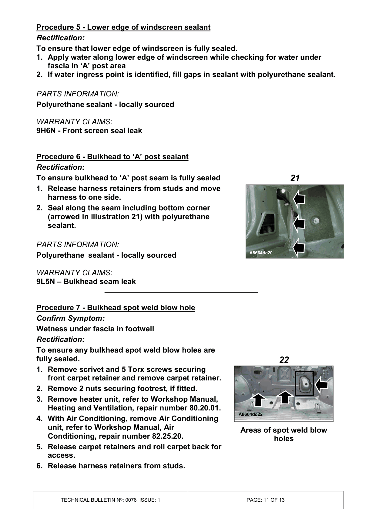
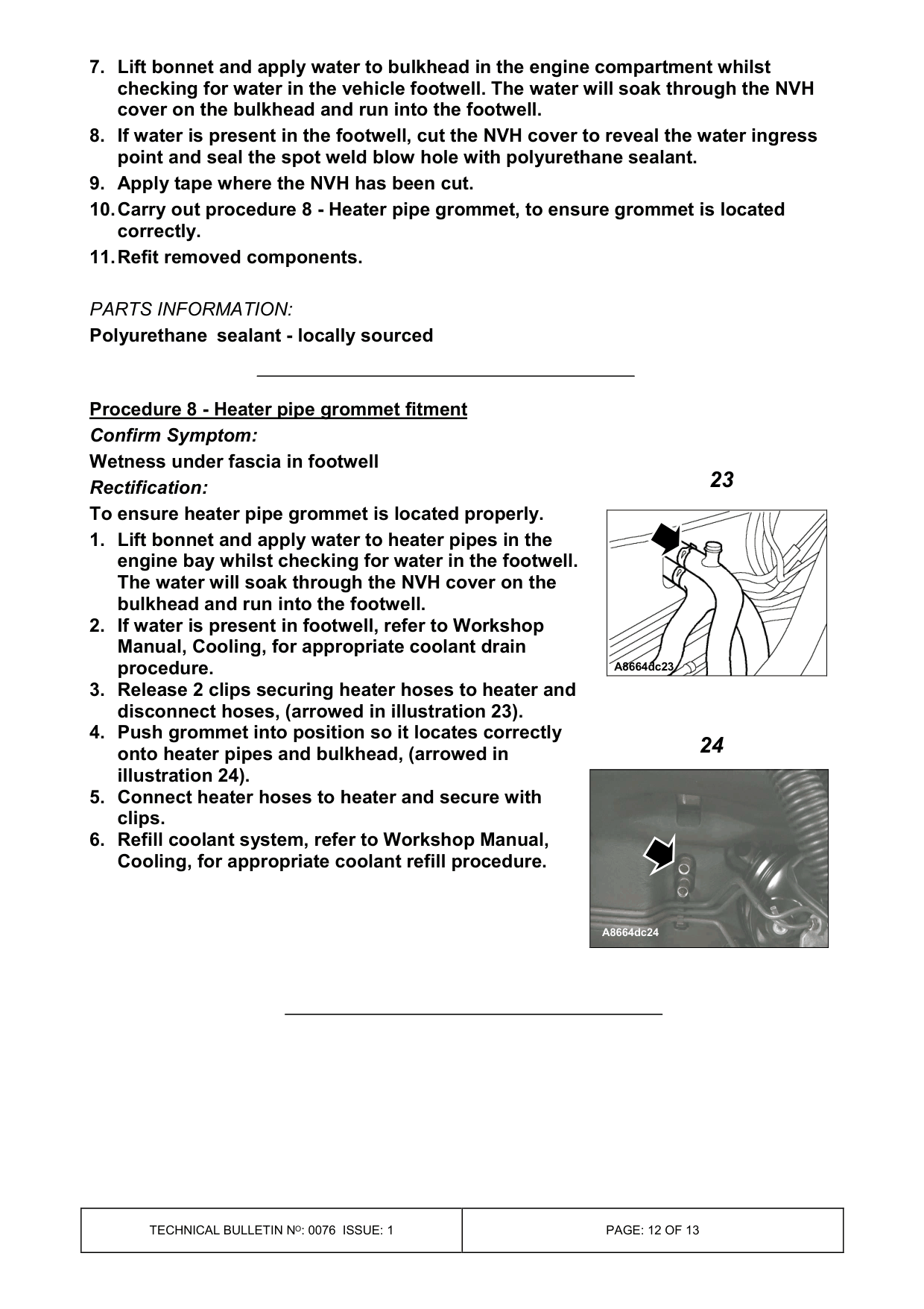
Procedure 3 - Windscreen aperture seams and Bonnet hinge sealant Confirm Symptom: Wetness at base of ‘A’ posts Rectification: To ensure that windscreen aperture and hinge seams are fully sealed. 1. Apply sealant to areas (arrowed in illustrations 17 and 18).
PARTS INFORMATION:
Polyurethane sealant - locally sourced
WARRANTY CLAIMS: 9H6N - Front screen seal leak 9F4N - Bonnet hinge leak
Procedure 4 - ‘A’ post to bulkhead sealant Rectification: To ensure that the plenum seams are fully sealed. 1. Seal around seam under plenum cover (arrowed in illustration 19), with polyurethane sealant. 2. Using aperture at side of plenum for access, apply sealant to the seam, (arrowed in illustration 20).
PARTS INFORMATION:
Polyurethane sealant - locally sourced
WARRANTY CLAIMS: 9L7N - Plenum seam leak
17
A8664dc16
18
A8664dc17
19
A8664dc18
20
A8664dc19
Procedure 5 - Lower edge of windscreen sealant Rectification: To ensure that lower edge of windscreen is fully sealed. 1. Apply water along lower edge of windscreen while checking for water under fascia in ‘A’ post area 2. If water ingress point is identified, fill gaps in sealant with polyurethane sealant.
PARTS INFORMATION:
Polyurethane sealant - locally sourced
WARRANTY CLAIMS: 9H6N - Front screen seal leak
Procedure 6 - Bulkhead to ‘A’ post sealant Rectification: To ensure bulkhead to ‘A’ post seam is fully sealed 1. Release harness retainers from studs and move harness to one side. 2. Seal along the seam including bottom corner (arrowed in illustration 21) with polyurethane sealant.
PARTS INFORMATION:
Polyurethane sealant - locally sourced
WARRANTY CLAIMS: 9L5N - Bulkhead seam leak
Procedure 7 - Bulkhead spot weld blow hole Confirm Symptom: Wetness under fascia in footwell Rectification: To ensure any bulkhead spot weld blow holes are fully sealed. 1. Remove scrivet and 5 Torx screws securing front carpet retainer and remove carpet retainer. 2. Remove 2 nuts securing footrest, if fitted. 3. Remove heater unit, refer to Workshop Manual, Heating and Ventilation, repair number 80.20.01. 4. With Air Conditioning, remove Air Conditioning unit, refer to Workshop Manual, Air Conditioning, repair number 82.25.20. 5. Release carpet retainers and roll carpet back for access. 6. Release harness retainers from studs.
21
A8664dc20
22
A8664dc22
Areas of spot weld blow holes
7. Lift bonnet and apply water to bulkhead in the engine compartment whilst checking for water in the vehicle footwell. The water will soak through the NVH cover on the bulkhead and run into the footwell. 8. If water is present in the footwell, cut the NVH cover to reveal the water ingress point and seal the spot weld blow hole with polyurethane sealant. 9. Apply tape where the NVH has been cut. 10. Carry out procedure 8 - Heater pipe grommet, to ensure grommet is located correctly. 11. Refit removed components.
PARTS INFORMATION:
Polyurethane sealant - locally sourced
Procedure 8 - Heater pipe grommet fitment Confirm Symptom: Wetness under fascia in footwell Rectification: To ensure heater pipe grommet is located properly. 1. Lift bonnet and apply water to heater pipes in the engine bay whilst checking for water in the footwell. The water will soak through the NVH cover on the bulkhead and run into the footwell. 2. If water is present in footwell, refer to Workshop Manual, Cooling, for appropriate coolant drain procedure. 3. Release 2 clips securing heater hoses to heater and disconnect hoses, (arrowed in illustration 23). 4. Push grommet into position so it locates correctly onto heater pipes and bulkhead, (arrowed in illustration 24). 5. Connect heater hoses to heater and secure with clips. 6. Refill coolant system, refer to Workshop Manual, Cooling, for appropriate coolant refill procedure.
23
A8664dc23
24
A8664dc24
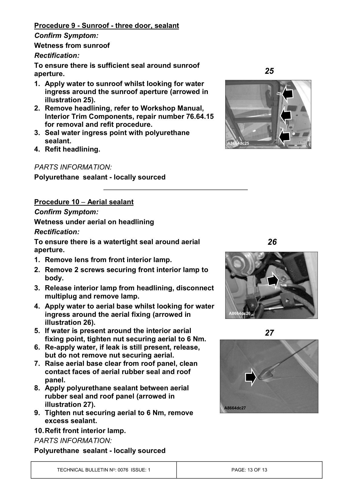
Procedure 9 - Sunroof - three door, sealant Confirm Symptom: Wetness from sunroof Rectification: To ensure there is sufficient seal around sunroof aperture. 1. Apply water to sunroof whilst looking for water ingress around the sunroof aperture (arrowed in illustration 25). 2. Remove headlining, refer to Workshop Manual, Interior Trim Components, repair number 76.64.15 for removal and refit procedure. 3. Seal water ingress point with polyurethane sealant. 4. Refit headlining.
PARTS INFORMATION:
Polyurethane sealant - locally sourced
Procedure 10 - Aerial sealant Confirm Symptom: Wetness under aerial on headlining Rectification: To ensure there is a watertight seal around aerial aperture. 1. Remove lens from front interior lamp. 2. Remove 2 screws securing front interior lamp to body. 3. Release interior lamp from headlining, disconnect multiplug and remove lamp. 4. Apply water to aerial base whilst looking for water ingress around the aerial fixing (arrowed in illustration 26). 5. If water is present around the interior aerial fixing point, tighten nut securing aerial to 6 Nm. 6. Re-apply water, if leak is still present, release, but do not remove nut securing aerial. 7. Raise aerial base clear from roof panel, clean contact faces of aerial rubber seal and roof panel. 8. Apply polyurethane sealant between aerial rubber seal and roof panel (arrowed in illustration 27). 9. Tighten nut securing aerial to 6 Nm, remove excess sealant. 10. Refit front interior lamp.
PARTS INFORMATION:
Polyurethane sealant - locally sourced
25
A8664dc25
26
A8664dc26
27
A8664dc27
Parts & tools for this job For Land Rover Freelander
- TOOLOBD2 scanner with SRSSearch: OBD2 scanner ABS SRS
- TOOLTrim removal tool kitSearch: trim removal tool kit
Links open Amazon search results in a new tab. As an Amazon Associate I earn from qualifying purchases.