
Hot air ‘bleed’ into cabin
- Make
- Land Rover
- Model
- Freelander Technical Bulletins
- Section
- Hot air ‘bleed’ into cabin › Hot air ‘bleed’ into cabin
HOT AIR ‘BLEED’ INTO CABIN
- Model
- Freelander
- Affected vehicles
- WA 600000 to YA 699999 Left hand drive derivatives with air conditioning in VIN ranges: YA 500000 to YA 576763
- Date
- 2001-07-18
- Reference
- Bulletin 0017, CDS ref L8613bu
Bulletin text
Freelander
AFFECTED RANGE:
Left hand drive derivatives with WA 600000 to YA 699999 air conditioning in VIN ranges: YA 500000 to YA 576763
PROBLEM:
HOT AIR ‘BLEED’ INTO CABIN The customer complains that the air conditioning system continues to emit hot air despite setting the air temperature control to the coldest position.
CAUSE:
Air, heated by the heater matrix, ‘bleeding’ past the heater blend flap into cabin.
ACTION:
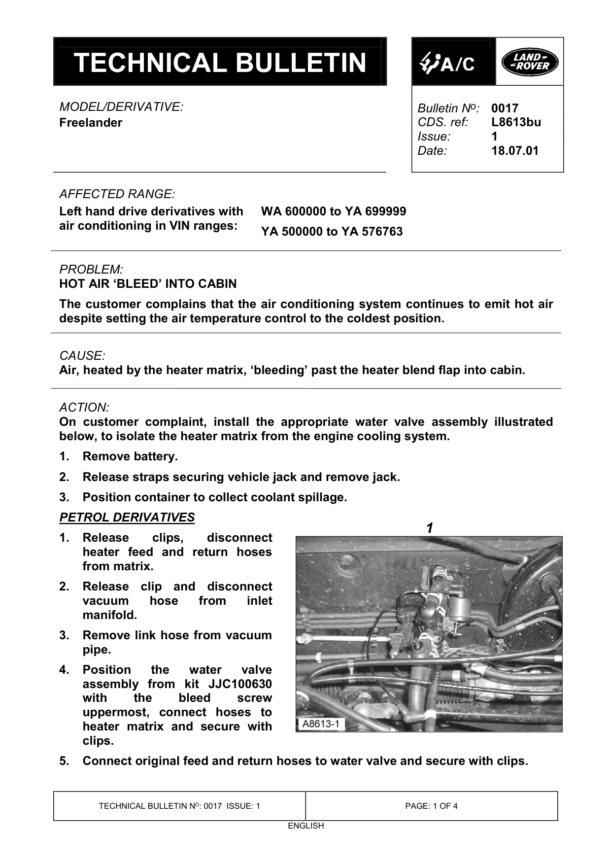
On customer complaint, install the appropriate water valve assembly illustrated below, to isolate the heater matrix from the engine cooling system. 1. Remove battery. 2. Release straps securing vehicle jack and remove jack. 3. Position container to collect coolant spillage. PETROL DERIVATIVES 1. Release clips, disconnect heater feed and return hoses from matrix. 2. Release clip and disconnect vacuum hose from inlet manifold. 3. Remove link hose from vacuum pipe. 4. Position the water valve assembly from kit JJC100630 with the bleed screw uppermost, connect hoses to heater matrix and secure with clips. 5. Connect original feed and return hoses to water valve and secure with clips.
Bulletin N o : 0017
1
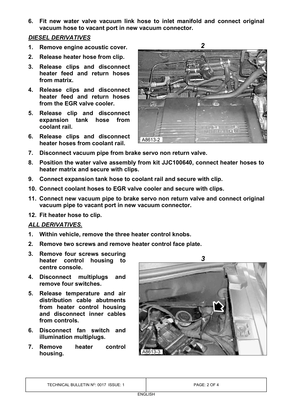
6. Fit new water valve vacuum link hose to inlet manifold and connect original vacuum hose to vacant port in new vacuum connector. DIESEL DERIVATIVES 1. Remove engine acoustic cover. 2. Release heater hose from clip. 3. Release clips and disconnect heater feed and return hoses from matrix. 4. Release clips and disconnect heater feed and return hoses from the EGR valve cooler. 5. Release clip and disconnect expansion tank hose from coolant rail. 6. Release clips and disconnect heater hoses from coolant rail. 7. Disconnect vacuum pipe from brake servo non return valve. 8. Position the water valve assembly from kit JJC100640, connect heater hoses to heater matrix and secure with clips. 9. Connect expansion tank hose to coolant rail and secure with clip. 10. Connect coolant hoses to EGR valve cooler and secure with clips. 11. Connect new vacuum pipe to brake servo non return valve and connect original vacuum pipe to vacant port in new vacuum connector. 12. Fit heater hose to clip. ALL DERIVATIVES. 1. Within vehicle, remove the three heater control knobs. 2. Remove two screws and remove heater control face plate. 3. Remove four screws securing heater control housing to centre console. 4. Disconnect multiplugs and remove four switches. 5. Release temperature and air distribution cable abutments from heater control housing and disconnect inner cables from controls. 6. Disconnect fan switch and illumination multiplugs. 7. Remove heater control housing.
2
3
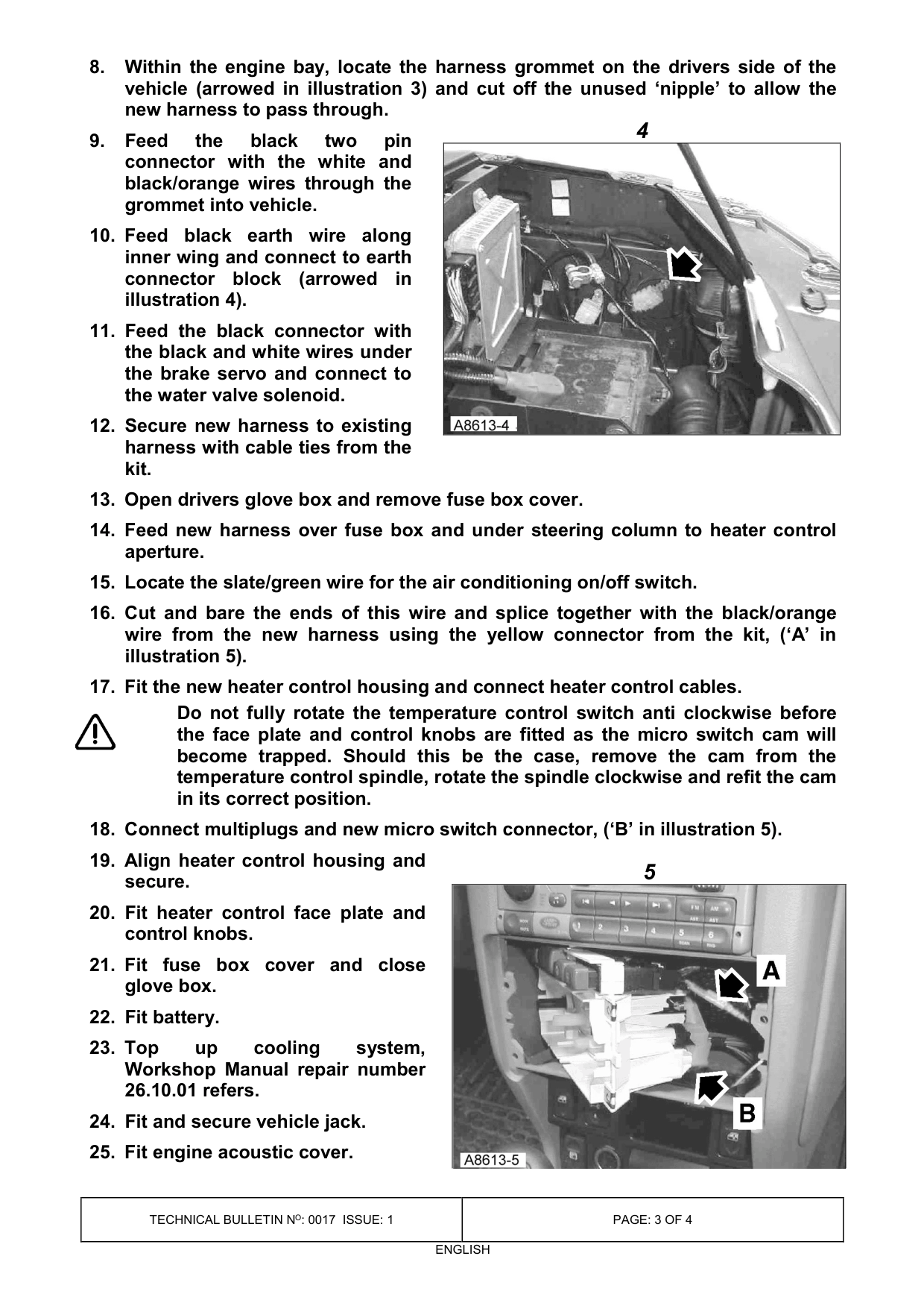
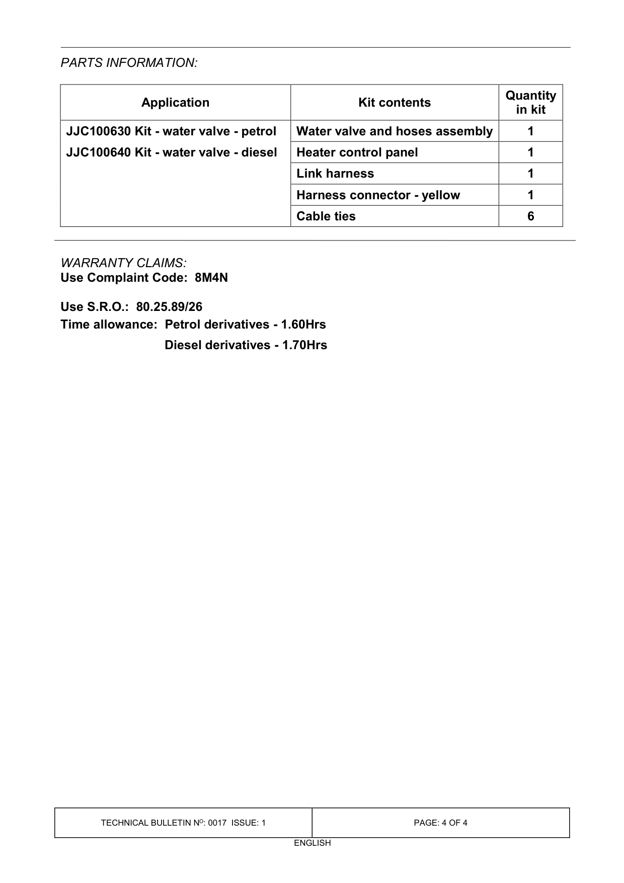
8. Within the engine bay, locate the harness grommet on the drivers side of the vehicle (arrowed in illustration 3) and cut off the unused ‘nipple’ to allow the new harness to pass through. 9. Feed the black two pin connector with the white and black/orange wires through the grommet into vehicle. 10. Feed black earth wire along inner wing and connect to earth connector block (arrowed in illustration 4). 11. Feed the black connector with the black and white wires under the brake servo and connect to the water valve solenoid. 12. Secure new harness to existing harness with cable ties from the kit. 13. Open drivers glove box and remove fuse box cover. 14. Feed new harness over fuse box and under steering column to heater control aperture. 15. Locate the slate/green wire for the air conditioning on/off switch. 16. Cut and bare the ends of this wire and splice together with the black/orange wire from the new harness using the yellow connector from the kit, (‘A’ in illustration 5). 17. Fit the new heater control housing and connect heater control cables. Do not fully rotate the temperature control switch anti clockwise before the face plate and control knobs are fitted as the micro switch cam will become trapped. Should this be the case, remove the cam from the temperature control spindle, rotate the spindle clockwise and refit the cam in its correct position. 18. Connect multiplugs and new micro switch connector, (‘B’ in illustration 5). 19. Align heater control housing and secure. 20. Fit heater control face plate and control knobs. 21. Fit fuse box cover and close glove box. 22. Fit battery. 23. Top up cooling system, Workshop Manual repair number 26.10.01 refers. 24. Fit and secure vehicle jack. 25. Fit engine acoustic cover.
4
5
PARTS INFORMATION:
Application
JJC100630 Kit - water valve - petrol JJC100640 Kit - water valve - diesel
WARRANTY CLAIMS: Use Complaint Code: 8M4N
Use S.R.O.: 80.25.89/26 Time allowance: Petrol derivatives - 1.60Hrs Diesel derivatives - 1.70Hrs
Quantity Kit contents in kit Water valve and hoses assembly 1 Heater control panel 1 Link harness 1 Harness connector - yellow 1 Cable ties 6
Parts & tools for this job For Land Rover Freelander
- TOOLBrake bleeder kitSearch: one man brake bleeder kit
- FLUIDBrake fluidSearch: brake fluid
- TOOLBrake line flaring toolSearch: brake line flaring tool
Links open Amazon search results in a new tab. As an Amazon Associate I earn from qualifying purchases.