
Propeller shaft assembly – repairs
- Make
- Land Rover
- Model
- Freelander Technical Bulletins
- Section
- Propeller shaft assembly – repairs › Propeller shaft assembly – repairs
PROPELLER SHAFT ASSEMBLY – REPAIRS
- Model
- Freelander
- Affected vehicles
- All vehicles
- Date
- 2000-01-26
- Reference
- Bulletin 0006, CDS ref L8550bu
Bulletin text
Freelander
AFFECTED RANGE:
All vehicles
PROBLEM:
PROPELLER SHAFT ASSEMBLY - REPAIRS
Replacement of complete propeller shaft assemblies when a more economical repair would be practical.
CAUSE:
Revised propeller shaft replacement / repair procedures and all individual parts are now available.
ACTION:
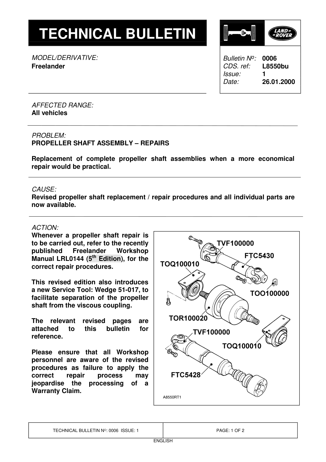
Whenever a propeller shaft repair is to be carried out, refer to the recently published Freelander Manual LRL0144 (5 th Edition), for the correct repair procedures.
This revised edition also introduces a new Service Tool: Wedge 51-017, to facilitate separation of the propeller shaft from the viscous coupling.
The relevant revised pages are attached to this bulletin for reference.
Please ensure that all personnel are aware of the revised procedures as failure to apply the correct repair process may jeopardise the processing of a Warranty Claim.
Bulletin N o : 0006 L8550bu 1 26.01.2000
PARTS INFORMATION:
Refer to the Parts Microfiche / Electronic Parts Catalogue to confirm correct part number details as required.
WARRANTY CLAIMS: Refer to the Repair Operation Times Manual for individual SRO numbers and repair times.
In future, Warranty Claims for the renewal of complete propeller shaft assemblies where only an individual component is faulty, will not be accepted.
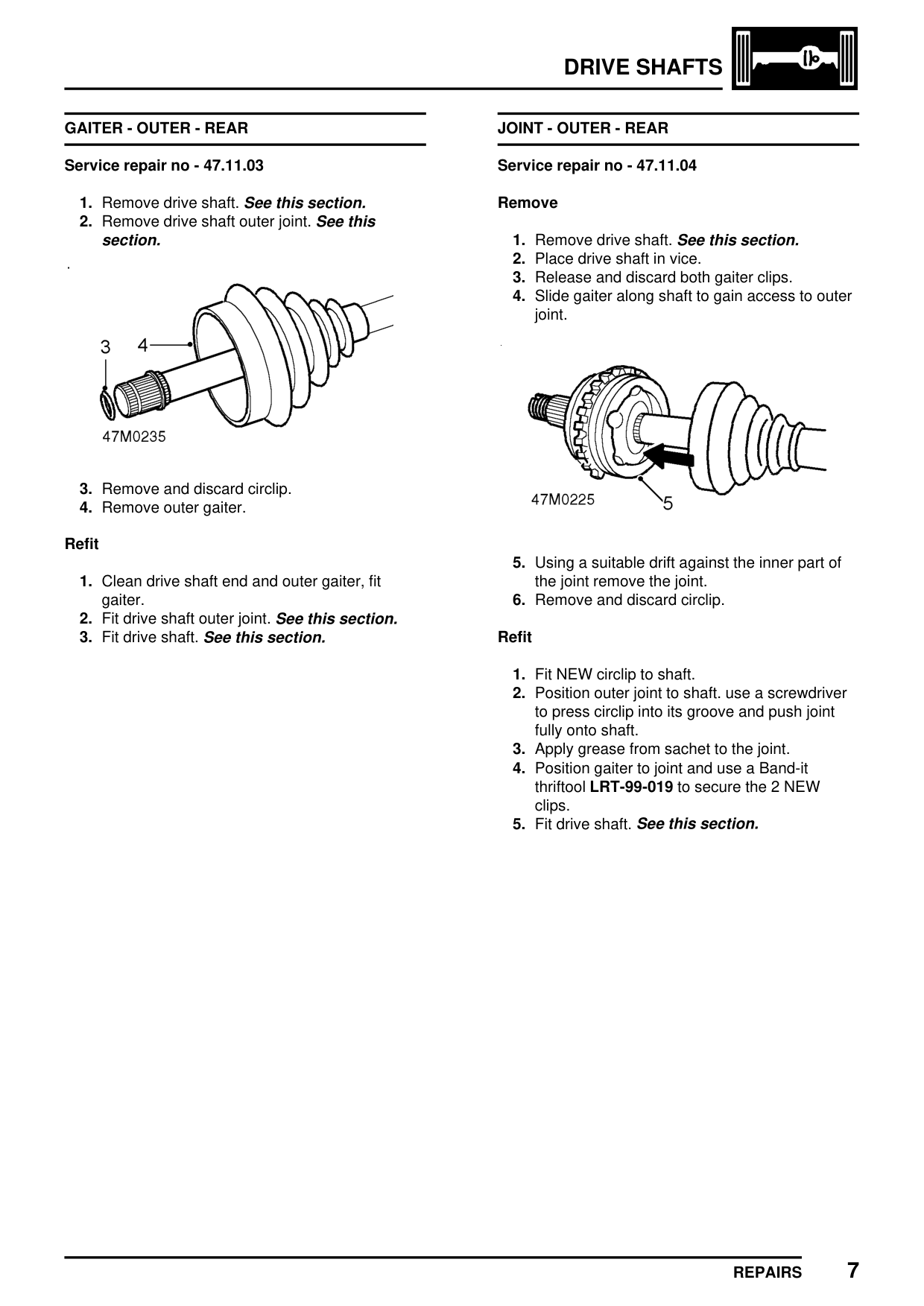
GAITER - OUTER - REAR
Service repair no - 47.11.03
1. Remove drive shaft. See this section. 2. Remove drive shaft outer joint. See this section.
3. Remove and discard circlip. 4. Remove outer gaiter.
Refit
1. Clean drive shaft end and outer gaiter, fit gaiter. 2. Fit drive shaft outer joint. See this section. 3. Fit drive shaft. See this section.
DRIVE SHAFTS
JOINT - OUTER - REAR
Service repair no - 47.11.04
Remove
1. Remove drive shaft. See this section. 2. Place drive shaft in vice. 3. Release and discard both gaiter clips. 4. Slide gaiter along shaft to gain access to outer joint.
5. Using a suitable drift against the inner part of the joint remove the joint. 6. Remove and discard circlip.
Refit
1. Fit NEW circlip to shaft. 2. Position outer joint to shaft. use a screwdriver to press circlip into its groove and push joint fully onto shaft. 3. Apply grease from sachet to the joint. 4. Position gaiter to joint and use a Band-it thriftool LRT-99-019 to secure the 2 NEW clips. 5. Fit drive shaft. See this section.
7 REPAIRS
DRIVE SHAFTS
PROPELLER SHAFT - ASSEMBLY
Service repair no - 47.15.01
Remove
1. Raise vehicle on a 4 post ramp.
NOTE: Raise one wheel on each axle for rotation of propeller shaft as necessary to access fixings.
CAUTION: When working on the propeller shafts:
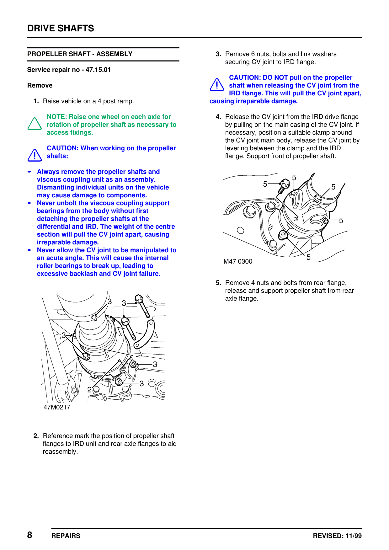
Always remove the propeller shafts and • viscous coupling unit as an assembly. Dismantling individual units on the vehicle may cause damage to components. Never unbolt the viscous coupling support • bearings from the body without first detaching the propeller shafts at the differential and IRD. The weight of the centre section will pull the CV joint apart, causing irreparable damage. Never allow the CV joint to be manipulated to • an acute angle. This will cause the internal roller bearings to break up, leading to excessive backlash and CV joint failure.
2. Reference mark the position of propeller shaft flanges to IRD unit and rear axle flanges to aid reassembly.
8 REPAIRS
3. Remove 6 nuts, bolts and link washers securing CV joint to IRD flange.
CAUTION: DO NOT pull on the propeller shaft when releasing the CV joint from the IRD flange. This will pull the CV joint apart, causing irreparable damage.
4. Release the CV joint from the IRD drive flange by pulling on the main casing of the CV joint. If necessary, position a suitable clamp around the CV joint main body, release the CV joint by levering between the clamp and the IRD flange. Support front of propeller shaft.
5. Remove 4 nuts and bolts from rear flange, release and support propeller shaft from rear axle flange.
REVISED: 11/99
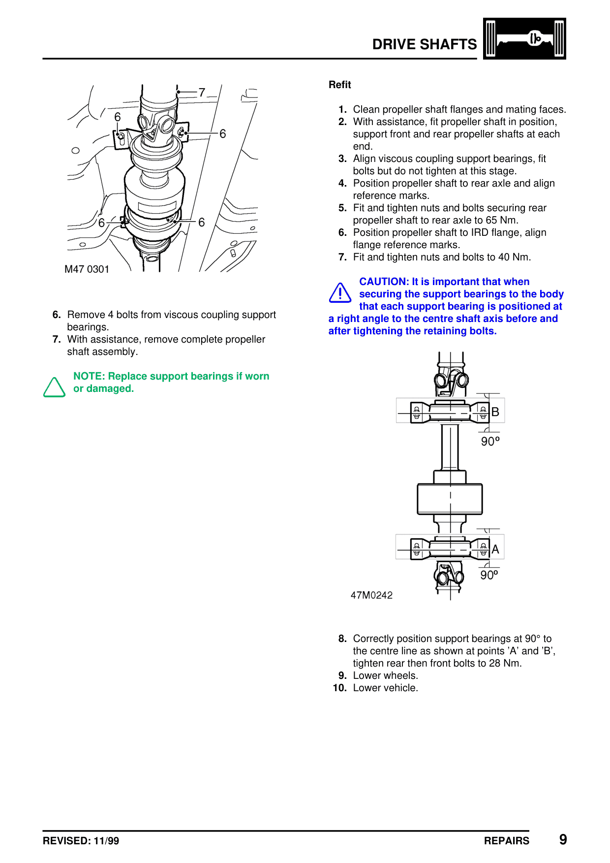
6. Remove 4 bolts from viscous coupling support bearings. 7. With assistance, remove complete propeller shaft assembly.
NOTE: Replace support bearings if worn or damaged.
REVISED: 11/99
DRIVE SHAFTS
Refit
1. Clean propeller shaft flanges and mating faces. 2. With assistance, fit propeller shaft in position, support front and rear propeller shafts at each end. 3. Align viscous coupling support bearings, fit bolts but do not tighten at this stage. 4. Position propeller shaft to rear axle and align reference marks. 5. Fit and tighten nuts and bolts securing rear propeller shaft to rear axle to 65 Nm. 6. Position propeller shaft to IRD flange, align flange reference marks. 7. Fit and tighten nuts and bolts to 40 Nm.
CAUTION: It is important that when securing the support bearings to the body that each support bearing is positioned at a right angle to the centre shaft axis before and after tightening the retaining bolts.
8. Correctly position support bearings at 90 ° to the centre line as shown at points ’A’ and ’B’, tighten rear then front bolts to 28 Nm. 9. Lower wheels. 10. Lower vehicle.
9 REPAIRS
DRIVE SHAFTS
PROPELLER SHAFT
Service repair no - 47.15.02 - propeller shaft - front Service repair no - 47.15.03 - propeller shaft - rear
Remove
1. Remove propeller shaft assembly. See this section.
CAUTION: It is important that the propeller shaft assembly is supported on a firm surface before separating the propeller shaft from the viscous coupling.
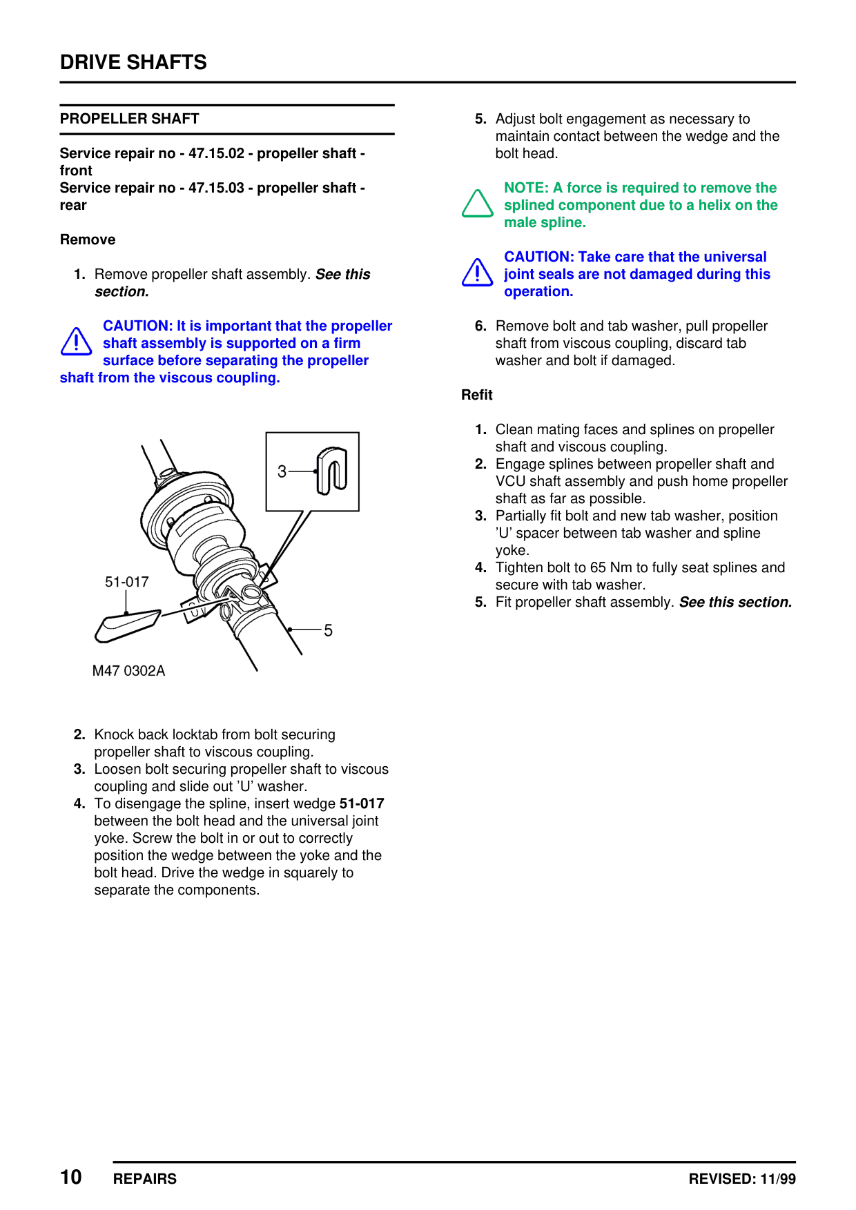
2. Knock back locktab from bolt securing propeller shaft to viscous coupling. 3. Loosen bolt securing propeller shaft to viscous coupling and slide out ’U’ washer. 4. To disengage the spline, insert wedge 51-017 between the bolt head and the universal joint yoke. Screw the bolt in or out to correctly position the wedge between the yoke and the bolt head. Drive the wedge in squarely to separate the components.
10 REPAIRS
5. Adjust bolt engagement as necessary to maintain contact between the wedge and the bolt head.
NOTE: A force is required to remove the splined component due to a helix on the male spline.
CAUTION: Take care that the universal joint seals are not damaged during this operation.
6. Remove bolt and tab washer, pull propeller shaft from viscous coupling, discard tab washer and bolt if damaged.
Refit
1. Clean mating faces and splines on propeller shaft and viscous coupling. 2. Engage splines between propeller shaft and VCU shaft assembly and push home propeller shaft as far as possible. 3. Partially fit bolt and new tab washer, position ’U’ spacer between tab washer and spline yoke. 4. Tighten bolt to 65 Nm to fully seat splines and secure with tab washer. 5. Fit propeller shaft assembly. See this section.
REVISED: 11/99
PROPELLER SHAFT - FRONT/REAR - OVERHAUL
Service repair no - 47.15.11 - propeller shaft - front Service repair no - 47.15.12 - propeller shaft - rear
Remove
1. Remove front or rear propeller shaft as applicable. See this section. 2. Thoroughly examine universal joint for signs of damage or wear. 3. Clean universal joint bearing cups and circlips.
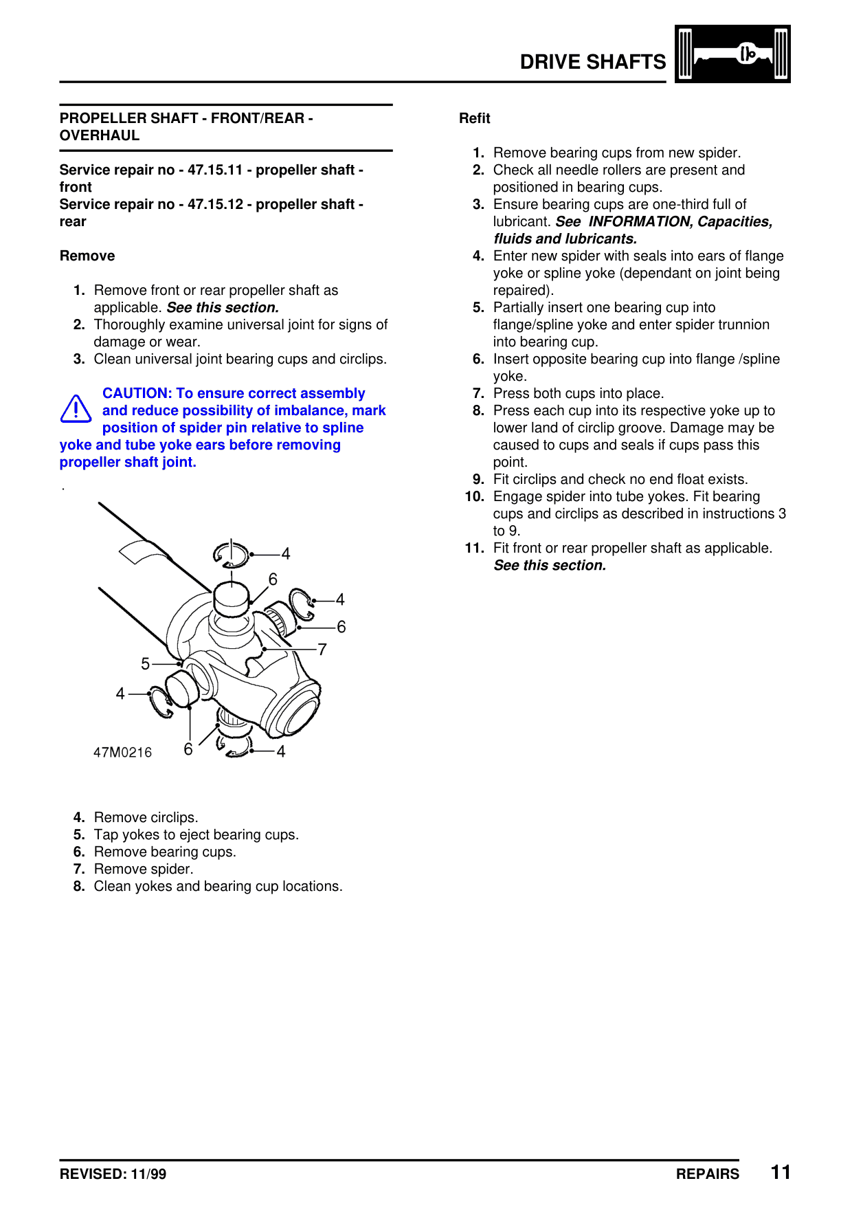
CAUTION: To ensure correct assembly and reduce possibility of imbalance, mark position of spider pin relative to spline yoke and tube yoke ears before removing propeller shaft joint.
4. Remove circlips. 5. Tap yokes to eject bearing cups. 6. Remove bearing cups. 7. Remove spider. 8. Clean yokes and bearing cup locations.
REVISED: 11/99
DRIVE SHAFTS
Refit
1. Remove bearing cups from new spider. 2. Check all needle rollers are present and positioned in bearing cups. 3. Ensure bearing cups are one-third full of lubricant. See INFORMATION, Capacities, fluids and lubricants. 4. Enter new spider with seals into ears of flange yoke or spline yoke (dependant on joint being repaired). 5. Partially insert one bearing cup into flange/spline yoke and enter spider trunnion into bearing cup. 6. Insert opposite bearing cup into flange /spline yoke. 7. Press both cups into place. 8. Press each cup into its respective yoke up to lower land of circlip groove. Damage may be caused to cups and seals if cups pass this point. 9. Fit circlips and check no end float exists. 10. Engage spider into tube yokes. Fit bearing cups and circlips as described in instructions 3 to 9. 11. Fit front or rear propeller shaft as applicable. See this section.
11 REPAIRS
DRIVE SHAFTS
VISCOUS COUPLING ASSEMBLY
Service repair no - 47.20.01
Remove
1. Remove front propeller shaft. See this section.
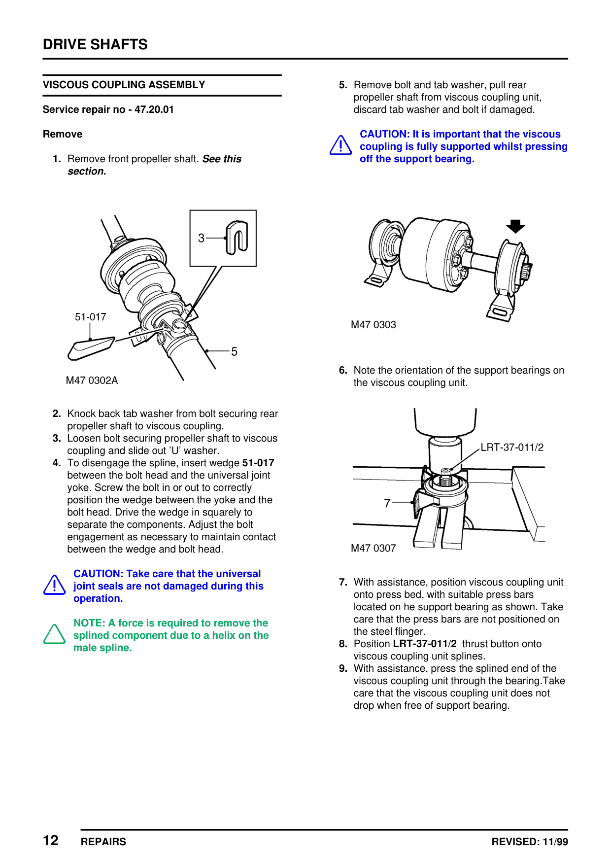
2. Knock back tab washer from bolt securing rear propeller shaft to viscous coupling. 3. Loosen bolt securing propeller shaft to viscous coupling and slide out ’U’ washer. 4. To disengage the spline, insert wedge 51-017 between the bolt head and the universal joint yoke. Screw the bolt in or out to correctly position the wedge between the yoke and the bolt head. Drive the wedge in squarely to separate the components. Adjust the bolt engagement as necessary to maintain contact between the wedge and bolt head.
CAUTION: Take care that the universal joint seals are not damaged during this operation.
NOTE: A force is required to remove the splined component due to a helix on the male spline.
12 REPAIRS
5. Remove bolt and tab washer, pull rear propeller shaft from viscous coupling unit, discard tab washer and bolt if damaged.
CAUTION: It is important that the viscous coupling is fully supported whilst pressing off the support bearing.
6. Note the orientation of the support bearings on the viscous coupling unit.
7. With assistance, position viscous coupling unit onto press bed, with suitable press bars located on he support bearing as shown. Take care that the press bars are not positioned on the steel flinger. 8. Position LRT-37-011/2 thrust button onto viscous coupling unit splines. 9. With assistance, press the splined end of the viscous coupling unit through the bearing.Take care that the viscous coupling unit does not drop when free of support bearing.
REVISED: 11/99
10. Repeat the procedure and remove the front support bearing from the viscous coupling unit. 11. Remove 3 bolts securing torsional vibration absorber to the viscous coupling unit. 12. Note orientation of torsional vibration absorber on viscous coupling unit.
Refit
NOTE: Replace support bearings if worn or damaged.
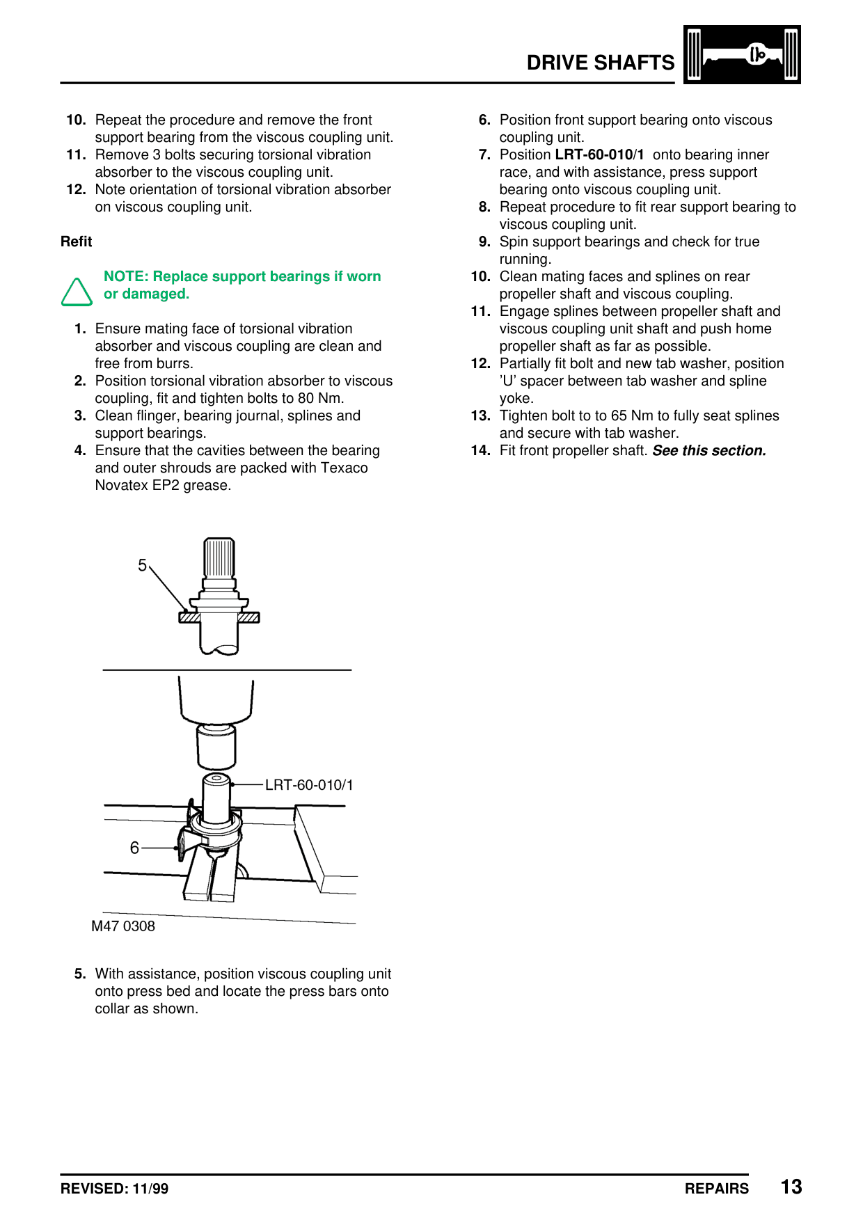
1. Ensure mating face of torsional vibration absorber and viscous coupling are clean and free from burrs. 2. Position torsional vibration absorber to viscous coupling, fit and tighten bolts to 80 Nm. 3. Clean flinger, bearing journal, splines and support bearings. 4. Ensure that the cavities between the bearing and outer shrouds are packed with Texaco Novatex EP2 grease.
5. With assistance, position viscous coupling unit onto press bed and locate the press bars onto collar as shown.
REVISED: 11/99
DRIVE SHAFTS
6. Position front support bearing onto viscous coupling unit. 7. Position LRT-60-010/1 onto bearing inner race, and with assistance, press support bearing onto viscous coupling unit. 8. Repeat procedure to fit rear support bearing to viscous coupling unit. 9. Spin support bearings and check for true running. 10. Clean mating faces and splines on rear propeller shaft and viscous coupling. 11. Engage splines between propeller shaft and viscous coupling unit shaft and push home propeller shaft as far as possible. 12. Partially fit bolt and new tab washer, position ’U’ spacer between tab washer and spline yoke. 13. Tighten bolt to to 65 Nm to fully seat splines and secure with tab washer. 14. Fit front propeller shaft. See this section.
13 REPAIRS
DRIVE SHAFTS
SUPPORT BEARING - VISCOUS COUPLING - FRONT
Service repair no - 47.20.05
Remove
1. Remove front propeller shaft. See this section.
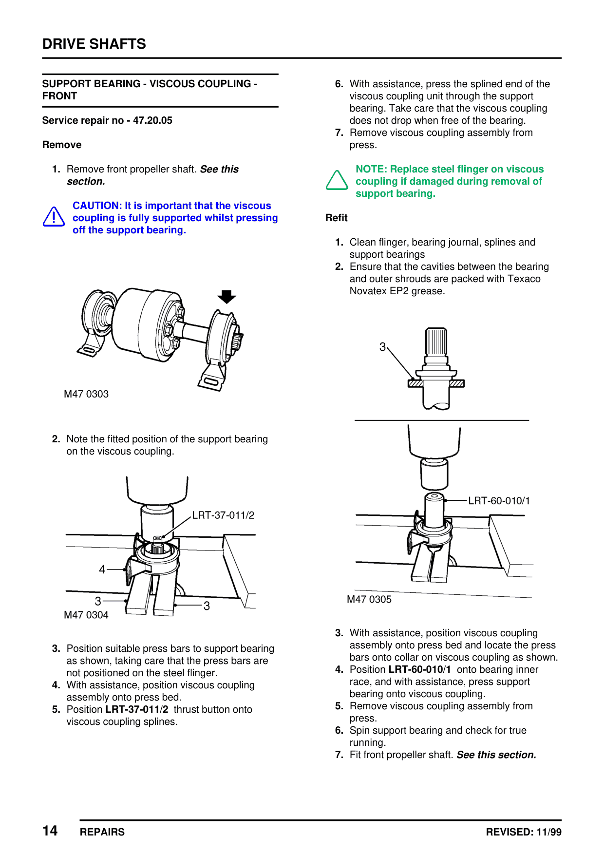
CAUTION: It is important that the viscous coupling is fully supported whilst pressing off the support bearing.
2. Note the fitted position of the support bearing on the viscous coupling.
3. Position suitable press bars to support bearing as shown, taking care that the press bars are not positioned on the steel flinger. 4. With assistance, position viscous coupling assembly onto press bed. 5. Position LRT-37-011/2 thrust button onto viscous coupling splines.
14 REPAIRS
6. With assistance, press the splined end of the viscous coupling unit through the support bearing. Take care that the viscous coupling does not drop when free of the bearing. 7. Remove viscous coupling assembly from press.
NOTE: Replace steel flinger on viscous coupling if damaged during removal of support bearing.
Refit
1. Clean flinger, bearing journal, splines and support bearings 2. Ensure that the cavities between the bearing and outer shrouds are packed with Texaco Novatex EP2 grease.
3. With assistance, position viscous coupling assembly onto press bed and locate the press bars onto collar on viscous coupling as shown. 4. Position LRT-60-010/1 onto bearing inner race, and with assistance, press support bearing onto viscous coupling. 5. Remove viscous coupling assembly from press. 6. Spin support bearing and check for true running. 7. Fit front propeller shaft. See this section.
REVISED: 11/99
SUPPORT BEARING - VISCOUS COUPLING - REAR
Service repair no - 47.20.06
Remove
1. Remove rear propeller shaft. See this section.
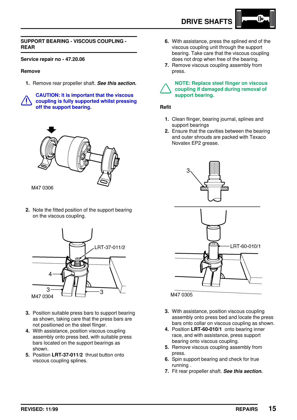
CAUTION: It is important that the viscous coupling is fully supported whilst pressing off the support bearing.
2. Note the fitted position of the support bearing on the viscous coupling.
3. Position suitable press bars to support bearing as shown, taking care that the press bars are not positioned on the steel flinger. 4. With assistance, position viscous coupling assembly onto press bed, with suitable press bars located on the support bearings as shown. 5. Position LRT-37-011/2 thrust button onto viscous coupling splines.
REVISED: 11/99
DRIVE SHAFTS
6. With assistance, press the splined end of the viscous coupling unit through the support bearing. Take care that the viscous coupling does not drop when free of the bearing. 7. Remove viscous coupling assembly from press.
NOTE: Replace steel flinger on viscous coupling if damaged during removal of support bearing.
Refit
1. Clean flinger, bearing journal, splines and support bearings 2. Ensure that the cavities between the bearing and outer shrouds are packed with Texaco Novatex EP2 grease.
3. With assistance, position viscous coupling assembly onto press bed and locate the press bars onto collar on viscous coupling as shown. 4. Position LRT-60-010/1 onto bearing inner race, and with assistance, press support bearing onto viscous coupling. 5. Remove viscous coupling assembly from press. 6. Spin support bearing and check for true running . 7. Fit rear propeller shaft. See this section.
15 REPAIRS
Parts & tools for this job For Land Rover Freelander
- TOOLTorque wrenchSearch: 3/8 inch torque wrench
- TOOLSocket setSearch: socket set metric
- BOOKHaynes manualSearch: Haynes manual Land Rover Freelander
Links open Amazon search results in a new tab. As an Amazon Associate I earn from qualifying purchases.