
L322 Range Rover System Description and Operation
AIR CONDITIONING
82-20
DESCRIPTION AND OPERATION
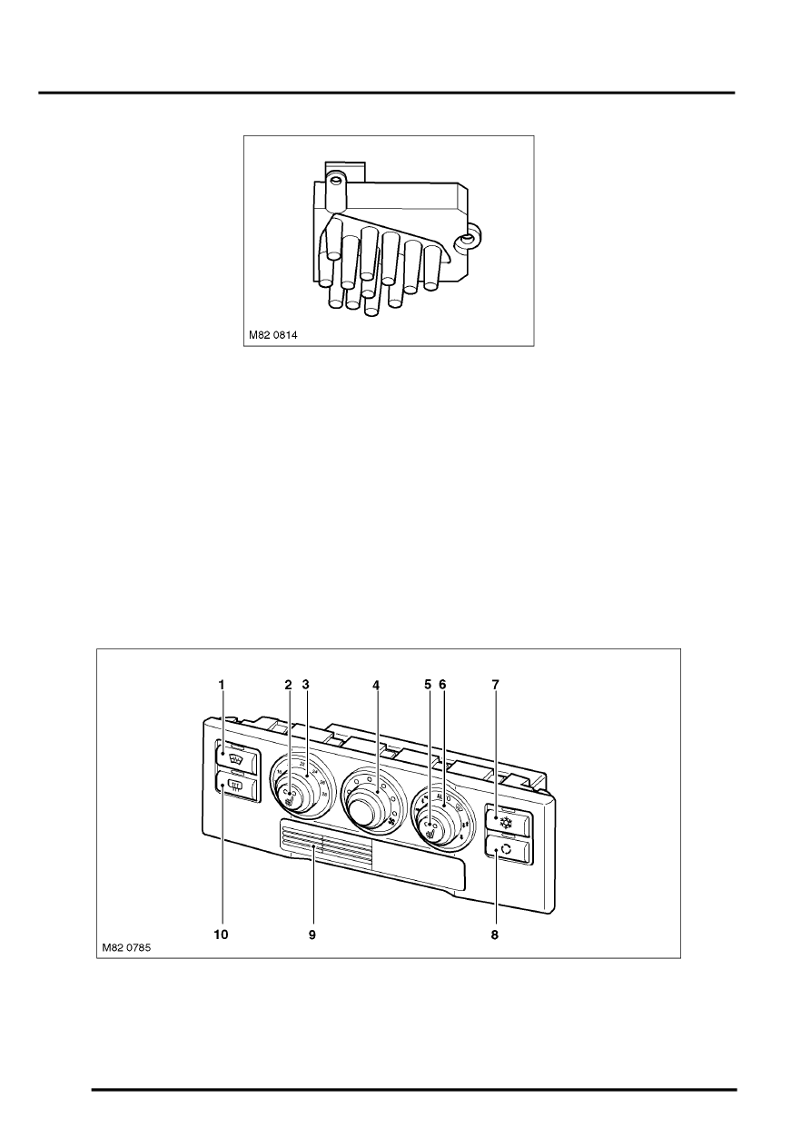
Rear Blower Output Stage
ATC ECU
The ATC ECU is installed in the centre of the fascia. An integral control panel contains push switches and rotary
switches/knobs for system control inputs. Orange tell-tale LED's in the switches and switch surrounds illuminate to
indicate the current settings of the system. The rotary temperature switch is graduated in degrees Celsius, except on
USA vehicles, where it is graduated in degrees Fahrenheit.
An in-car temperature sensor and associated electric fan are installed behind a grille in the control panel.
The ATC ECU processes inputs from the control panel switches and system sensors, then outputs the appropriate
signals to control the A/C system. In addition to controlling the A/C system, the ATC ECU also controls the following:
l
The windscreen heater and windscreen wiper parking area heater (optional fit, not available on vehicles with infra
red protection glass)
l
The windscreen washer jet heaters
l
The rear window heater
l
The front seat heaters.
Low Line Control Panel
1 Windscreen heater switch
2 LH front seat heater switch
3 Temperature switch
4 Blower switch
5 RH front seat heater switch
6 Distribution control knob
7 A/C switch
8 Recirculation switch
9 In-car temperature sensor
10 Rear window heater switch