
L322 Range Rover AC Distribution Ducts Overview
AIR CONDITIONING
82-18
DESCRIPTION AND OPERATION
Control Flap Motors
Two types of electrical stepper motor are used to operate the control flaps in the heater assembly. A conventional 500
Hz stepper motor operates the recirculation flaps, on the low and high line systems. On the high line system, five bus
controlled 200 Hz stepper motors operate the ram air, distribution (windscreen, face level and footwell) and the rear
face level temperature control flaps. On the low line system a bus controlled stepper motor operates the distribution
flaps cam mechanism. All of the stepper motors are controlled by the ATC ECU. None of the stepper motors are
interchangeable.
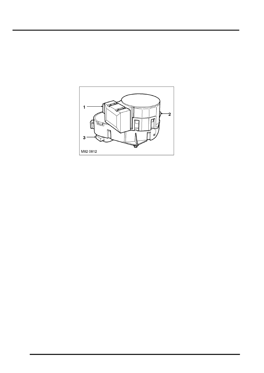
Typical Control Flap Motor
1 Electrical connector
2 Release clip
3 Output shaft
Each bus controlled stepper motor incorporates a microprocessor and is connected to an M bus from the ATC ECU,
which consists of three wires making up power, ground and signal circuits. The microprocessor in each bus controlled
stepper motor is programmed with a different address. Each M bus message from the ATC ECU contains the address
of an individual bus controlled stepper motor, so only that motor responds to the message.
None of the stepper motors incorporate a feedback potentiometer. Instead, the ATC ECU determines the positions of
the flaps by using either their closed or open position as a datum and memorising the steps that it drives the individual
stepper motors. Each time the ignition is switched on, the ATC ECU checks the memorised position of the stepper
motors against fixed values for the current system configuration. If there is an error (e.g. after a power supply failure
during operation or after replacement of the ATC ECU), the ATC ECU calibrates the applicable stepper motors, to re-
establish the datums, by driving them fully closed or open before re-setting them to their nominal position. A calibration
run can also be invoked using TestBook/T4.
When any of the control flaps are set to fully closed or open, the ATC ECU signals the related stepper motor to move
the appropriate number of steps in the applicable direction. To accommodate build tolerances and wear, and to
ensure the flaps are held in the selected position, every 20 seconds the ATC ECU signals the stepper motor to move
an additional 10 steps in the relevant direction.
Distribution Ducts
Air from the heater assembly is distributed around the vehicle interior through distribution ducts to outlets in the fascia,
the front and rear footwells, and the rear of the cubby box between the front seats.
In the fascia, the distribution ducts are connected to fixed vents for the windscreen and side windows and adjustable
vent assemblies for face level air. An adjustable vent assembly is also installed on the rear of the cubby box for rear
face level air. The footwell outlets are fixed vents formed in the end of the related distribution ducts.