
L322 Range Rover System Description and Operation
AUTOMATIC TRANSMISSION – ZF 5HP24
44-2-14 DESCRIPTION AND OPERATION
As the rotational speed of the engine and therefore the turbine increases, the direction of the fluid leaving the turbine
changes to path 'D'. The fluid is now directed from the turbine to the opposite side of the stator blades, rotating the
stator in the opposite direction. To prevent the stator from resisting the smooth flow of the fluid from the turbine, the
sprag clutch releases, allowing the stator to rotate freely on it shaft.
When the stator becomes inactive, the torque converter no longer multiples the engine torque. When the torque
converter reaches this operational condition it ceases to multiply the engine torque and acts solely as a fluid coupling,
with the impeller and the turbine rotating at approximately the same speed.
The stator uses a sprag type clutch. When the stator is rotated in a clockwise direction the sprags twist and are
wedged between the inner and outer races. In this condition the sprags transfer the rotation of the outer race to the
inner race which rotates at the same speed. Refer to 'One Way Freewheel Clutch' in this manual for further details of
the sprag type clutch.
Lock-up Clutch Mechanism
The Torque Converter Clutch (TCC) is hydraulically controlled by an electronic pressure regulating solenoid (EPRS4)
which is controlled by the EAT ECU. This allows the torque converter to have three states of operation as follows:
l
Fully engaged
l
Controlled slip variable engagement
l
Fully disengaged.
The TCC is controlled by two hydraulic spool valves located in the valve block. These valves are actuated by pilot
pressure supplied via a solenoid valve which is also located in the valve block. The solenoid valve is operated by PWM
signals from the EAT ECU to give full, partial or no lock-up of the torque converter.
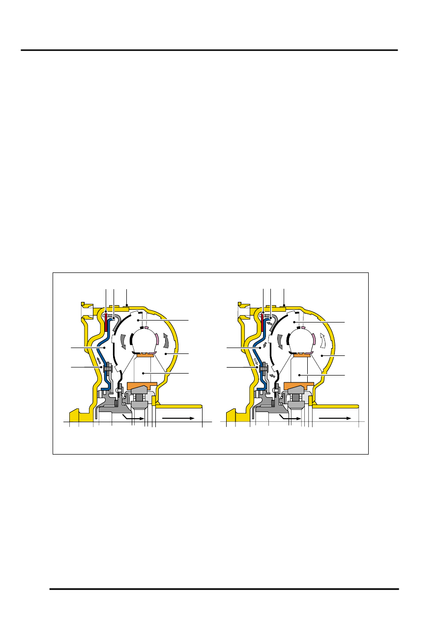
A = Unlocked condition
B = Locked condition
1 Clutch plate
2 Clutch piston
3 Torque converter body
4 Turbine
5 Impeller
6 Stator
7 Piston chamber
8 Turbine chamber
The lock-up clutch is a hydro-mechanical device which eliminates torque converter slip, improving fuel consumption.
The engagement and disengagement is controlled by the EAT ECU to allow a certain amount of controlled 'slip'. This
allows a small difference in the rotational speeds of the impeller and the turbine which results in improved shift quality.
The lock-up clutch comprises a piston and a clutch friction plate.
M44 1824
A
B
1
4
6
5
7
8
1
4
6
5
7
8
2
3
2
3