
Range Rover Automatic Transmission Valve Block and Solenoid Valves Description
AUTOMATIC TRANSMISSION – ZF 5HP24
DESCRIPTION AND OPERATION 44-2-17
Solenoid EPRS1 supplies a lower control pressure as the signal amperage increases. The EPRS1 solenoid is a
normally closed regulating flow solenoid valve and regulates the main line pressure. The solenoid is used for adaptive
pressure control. The EAT ECU operates the solenoid using PWM signals. The EAT ECU monitors engine load and
clutch slip and varies the solenoid duty cycle accordingly.
Solenoids EPRS2, 3 and 5 supply a higher control pressure as the signal amperage increases. The solenoids are
normally open solenoids regulating flow solenoid valves. The solenoids are used to regulate the supply of fluid
pressure for clutch application during overlap up and down shifts of gears 2–3, 3–4 and 4–5. The EAT ECU operates
the solenoids using a PWM earth proportional to the required increasing or decreasing clutch pressures.
The resistance of the coil winding for solenoid EPRS1 is between 5.4 to 6.4
Ω
at 20
°
C (68
°
F). The resistance of the
coil windings for solenoids EPRS2, 3, 4 and 5 is between 5.9 and 6.9
Ω
at 20
°
C (68
°
F).
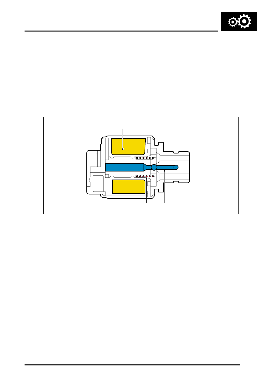
Shift Control Solenoids
1 Coil winding
2 Valve
3 Spring
Three shift control Solenoid Valves (SV) are located in the valve block. The solenoids are controlled by the EAT ECU
and convert electrical signals into hydraulic control signals to control clutch application.
The shift control solenoids SV1, 2 and 3 are normally closed, on/off solenoids which are controlled by the EAT ECU
switching the solenoid to earth. The EAT ECU also supplies the power to solenoids. The EAT ECU energises the
solenoids in a programmed sequence for clutch application for gear ratio changes and shift control.
The resistance of the coil winding for solenoids SV1, 2 and 3 is between 26 to 30.4
Ω
at 20
°
C (68
°
F).
Dampers
There are six dampers located in the valve block. Four of the dampers are used to regulate and dampen the regulated
pressure supplied via the pressure regulating solenoid valves. The two remaining dampers are used for operation of
clutches 'A' and 'C' and providing damping of the fluid pressure during shift changes. All of the dampers are load
dependent through modulation of the damper against its return spring pressure.
The dampers comprise a piston, a housing bore and a spring. The piston is subject to the pressure applied by the
spring. The bore has a connecting port to the function to which it applies. Fluid pressure applied to the applicable
component (i.e. a clutch) is also subjected to the full area of the piston, which moves against the opposing force
applied by the spring. The movement of the piston creates an action similar to a shock absorber, momentarily delaying
the build up of pressure in the circuit. This results in a more gradual application of clutches improving shift quality.
M44 1826
1
2
3