
ABS Modulator
- Make
- Land Rover
- Model
- Range Rover L322 Range Rover System Description and Operation
- Section
- Dynamic Stability Control › ABS Modulator
BRAKES
DESCRIPTION AND OPERATION
70-23
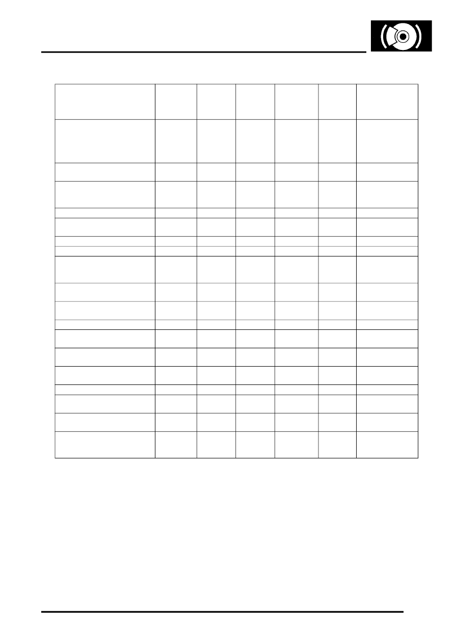
The following table describes the warning lamps, their associated faults and system response.
ABS Modulator
The ABS modulator controls the supply of hydraulic pressure to the brakes in response to inputs from the ABS ECU.
The modulator is attached by three mounting bushes to a bracket on the LH inner wing, and connected to the primary
and secondary hydraulic circuits downstream of the master cylinder assembly. Two electrical connectors link the ABS
modulator to the vehicle wiring. Internal passages in the ABS modulator, separated into primary and secondary
circuits, connect to the various components that control the supply of hydraulic pressure to the brakes. Valves and
check valves control the flow through the internal circuits. A damper chamber and restrictor are included in each circuit
to refine system operation. Inlet and outlet solenoid valves control the flow to the individual brakes. An expansion
chamber is connected to each circuit to absorb pressure. A return pump is connected to both circuits to provide a
pressure source.
System Status
Hand
Brake
Warning
Lamp
Brake
Warning
Lamp
ABS
Lamp
DSC Lamp
HDC
Lamp
Message Centre
Lamp check
On for 2
seconds
Amber for
1 second
then red
for 1
second
On for 2
seconds
On for 2
seconds
On for 2
seconds
ECU under voltage
On, red
and amber
On
On
Off
Hand brake On
On, red
Release park
brake (when
driving)
Low brake fluid level
On, red
Check brake fluid
Electric Brake Assist (EBA)
failure) ABS & EBD available)
On, amber
Off
ABS Failure (EBD available)
On, amber
On
On
Off
EBD failure
On, red
On
On
Off
DSC failure
On,
amber, or
red
On
On
Single gong 1st
time failure occurs
HDC failure
On, amber
or red
On
Off
HDC Inactive
DSC activity (including engine
intervention)
flash 2 Hz
ETC activity (brakes only)
DSC switched passive (TC
function still available)
On
ETC activity while DSC
switched passive
On
HDC switched on (not enabled
or fading out)
flash 2 Hz
HDC switched on and enabled
On
HDC temporarily unavailable
(brake overheat)
Off
HDC temp. Not
available
HDC switching off (due to high
speed in high range)
Off
No HDC - slow
down
Driver attempt to switch on
HDC at high speed in high
range
Off
No HDC - slow
down
Parts & tools for this job For Land Rover Range Rover
- TOOLOBD2 scanner with ABSSearch: OBD2 scanner ABS SRS
- TOOLDigital multimeterSearch: automotive digital multimeter
Links open Amazon search results in a new tab. As an Amazon Associate I earn from qualifying purchases.