L322 Range Rover System Description and Operation

INSTRUMENTS
88-8
DESCRIPTION AND OPERATION
This information is passed from the ABS ECU, on a hardwired connection, to the instrument pack and is received by
one of the microprocessors. The microprocessor applies a formula to the signal and calculates a numerical, 16 bit
value for the signal. This signal is then used by the speedometer drive to display the current speed to the driver. A
second digital signal output is also broadcast on the CAN, I and K buses for use by other systems.
To prevent incorrect readings due to spinning wheels, the microprocessor introduces a time delay on the output signal
if the received speed signal increases too quickly. The delay ensures that only the true speed is displayed and
transmitted on the bus systems.
Two versions of the speedometer display are used. One shows the speed in kilometres per hour and the other shows
the speed in miles per hour as the main display and kilometres per hour as a secondary display.
Tachometer
The tachometer is an electrically driven, analogue instrument for displaying the vehicle engine speed. The pointer
needle is oil damped to prevent impacts on the vehicle wheels, causing deflection of the pointer needle.
The tachometer is driven by an engine speed signal transmitted on the CAN from the ECM. The signal is in the form
of a square wave signal of variable frequency derived from the crankshaft position sensor. The signal is received by
one of the microprocessors which processes the signal. The output signal from the microprocessor is then used to
drive the tachometer.
Two versions of the tachometer are used for petrol and diesel engine variants. The petrol engine variants use a display
which has a maximum engine speed reading of 7000 rev/min. The diesel engine variants use a display which has a
maximum engine speed reading of 6000 rev/min.
Fuel Level Gauge
The fuel gauge is an electrically driven, analogue instrument for displaying the fuel tank contents. The pointer needle
is oil damped to prevent impacts on the vehicle wheels, causing deflection of the pointer needle. When the ignition is
off, the pointer returns to the empty position.
The instrument pack is connected to two tank level sensors. One sensor is located in each side of the saddle type fuel
tank and uses a float operated potentiometer for measuring the tank contents. Each tank level sensor is supplied with
a current from the instrument pack. The returned current, via the potentiometer of the sensor, is read by one of the
microprocessors. The reduced current from both sensors is evaluated and converted into a signal to position the fuel
gauge needle at the appropriate level reading. When the microprocessor determines that fuel tank contents have
reached a predetermined level, the low fuel level warning lamp is illuminated and a chime is emitted from the sounder
to alert the driver of the low fuel condition.
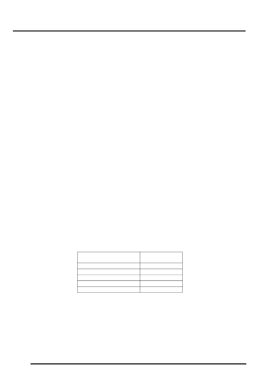
The following table shows potentiometer resistance values in relation to fuel tank contents and the fuel gauge display.
The figures are shown as a guide only because an infinite number of left/right sensor resistance values can be
obtained.
Two versions of the fuel level gauge are used. Markets with a kilometres only speedometer use a percentage gauge
reading marked 0 - 100%, with graduations of 0, 25, 50, 75 and max. Markets using miles and kilometres speedometer
readouts use an imperial fraction reading marked 0 - 1, with graduations of 0,
1
/
4
,
1
/
2
,
3
/
4
and 1.
Engine Coolant Temperature Gauge
The engine coolant temperature gauge is an electrically driven, analogue instrument for displaying the engine coolant
temperature to the driver. The pointer needle is oil damped to prevent impacts on the vehicle wheels causing
deflection of the pointer needle. When the ignition is off, the pointer returns to the cold position.
Tank Sensor Potentiometer
Resistance
Ω
Left/Right
Gauge Needle
Pointer Position
20 / 20
0
146 / 121
25% /
1
/
4
280 / 213
50% /
1
/
2
396 / 323
75% /
3
/
4
500 / 428
100% / 1/1
