
L322 Range Rover System Description and Operation
LIGHTING
DESCRIPTION AND OPERATION 86-2-25
Trailer Module
The trailer module is fitted to all vehicles and is located in the RH side of the luggage compartment, behind the
removable trim panel, adjacent to the rear fusebox. The module is required to separate the load circuits of the trailer
from the load circuits of the towing vehicle. This allows separate monitoring of the vehicle lamps and the trailer circuits.
The trailer module comprises a double transistor for reverse lamp and rear fog lamp operation and overload proof
MOSFET circuit breakers for the following lamps:
l
Left direction indicator
l
Right direction indicator
l
Brake lamps
l
Left tail lamp
l
Right tail lamp
l
Permanent trailer battery supply circuits.
The above lamps are connected to the trailer module via direct connections to the applicable lamps. The rear fog
lamps and reverse lamps are not directly connected to the lamps units because these lamps must be disabled when
the trailer socket is connected.
The LCM communicates with the trailer module via a bi-directional, dedicated serial link. The rear fog lamps and
reverse lamps are controlled on this link. The trailer module also uses this link to transmit error messages for the trailer
lamps to the LCM.
The trailer module has two modes of operation; sleep mode and normal mode. Sleep mode is initiated by the LCM
after a predetermined time. In this mode the trailer module processor clock speed is reduced to a minimum and all
loads are switched off to keep current consumption to a minimum. The module operates in normal mode on receipt
of an applicable message from the LCM. The required loads and the current supply for bulb failure detection are
activated.
The LCM communicates with the trailer module every 2 seconds with a normal mode telegram. If the trailer module
no longer responds, the data link to the module is switched low for 1 second after ten unsuccessful attempts to
establish the communication. When the LCM switches the data link low, the trailer module is 'reset'. If communication
is not established after thirty attempts in succession, the LCM assumes the module is defective and records an
applicable error message in the error memory.
If a replacement trailer module is fitted, the LCM instantly recognises it via the data link. Connection of TestBook/T4
is not required to establish communications between the LCM and the trailer module.
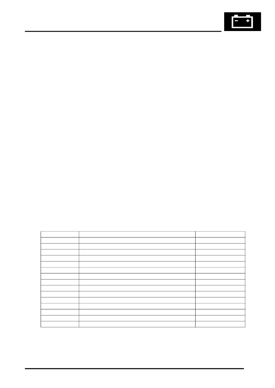
Trailer module Harness Connector C0380 Pin Details
Pin No.
Description
Input/Output
1
Brake lamps
Output
2
Reverse lamps
Output
3
Rear fog guard lamps
Output
4
LH tail lamp
Output
5
RH direction indicator lamp
Output
6
RH tail lamp
Output
7
LH direction indicator lamp
Output
8
Battery power supply
Input
9
Brake lamps
Input
10
RH direction indicator lamp
Input
11
LH tail lamp
Input
12
LH direction indicator lamp
Output
13
Serial interface with LCM
Input/Output
14
RH tail lamp
Output
15
Ground
–