
L322 Range Rover System Description and Operation
MANIFOLDS AND EXHAUST SYSTEM – V8
DESCRIPTION AND OPERATION
30-2-1
MANIFOLDS AND EXHAUST SYSTEM – V8
DESCRIPTION AND OPERATION
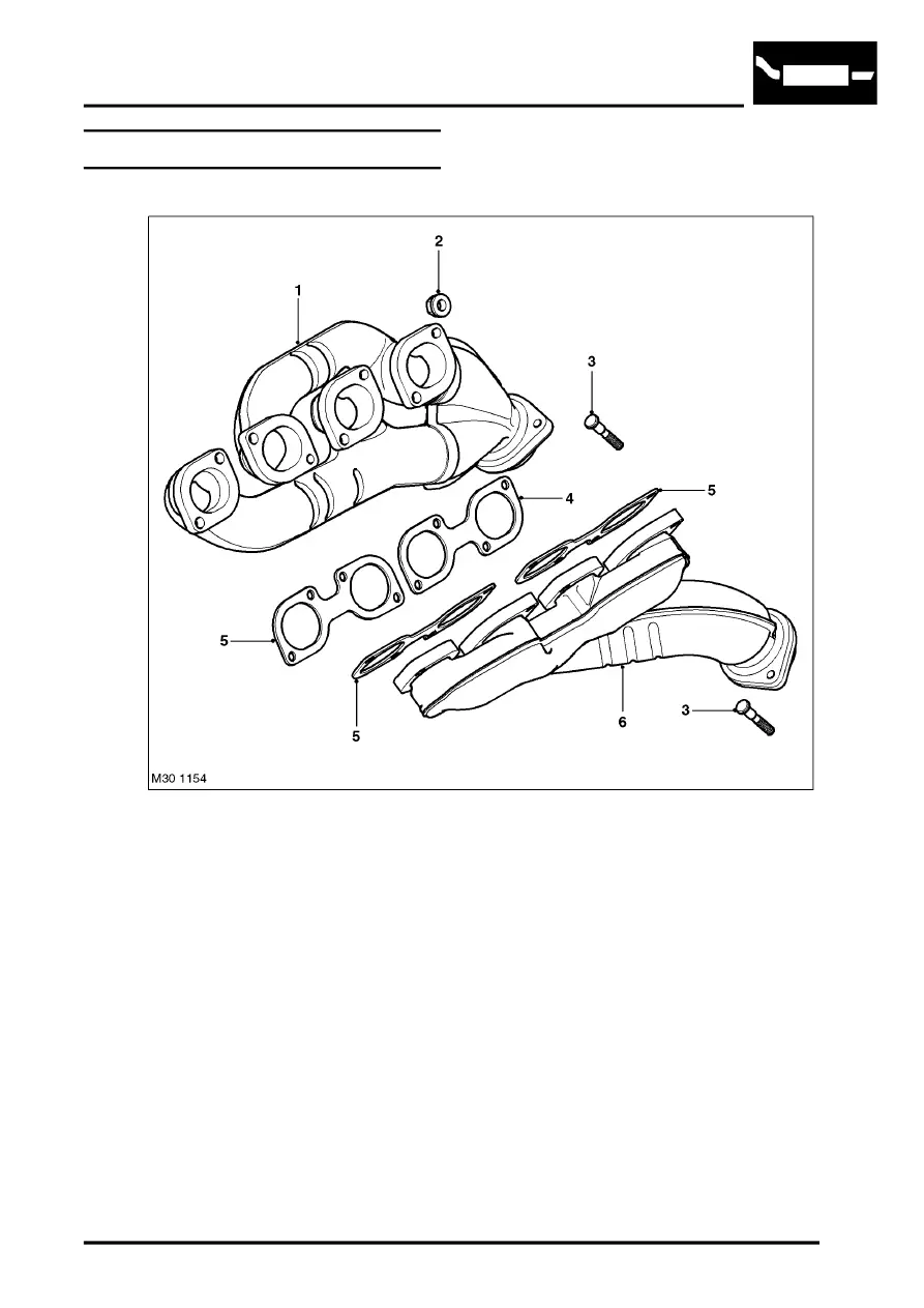
Exhaust Manifold Component Layout
1 Exhaust Manifold – Cylinders 1 – 4
2 Nut – (16 off)
3 Stud – Manifold to Exhaust Pipe — (4 off)
4 Gasket – cylinders 3 – 4
5 Gasket – cylinders 1 – 2, 5 – 6 and 7 – 8
6 Exhaust Manifold – Cylinders 5 – 8