
L322 Range Rover System Description and Operation
RESTRAINT SYSTEMS
75-16
DESCRIPTION AND OPERATION
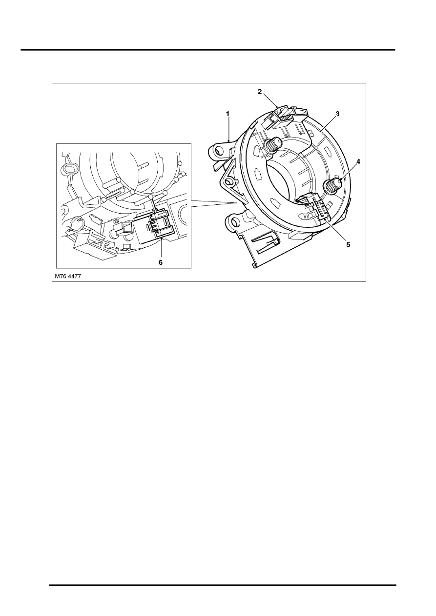
Rotary Coupler
1 Outer housing
2 Electrical connector
3 Inner housing
4 Drive spigot
5 Locking lever
6 Electrical connector
The rotary coupler is installed on the steering column to provide the electrical interface between the fixed wiring
harness and the steering wheel. The rotary coupler provides connections for the driver airbag, horn and steering
wheel switch packs.
A rotating link harness is encapsulated into a plastic cassette comprising outer and inner housings with integral
connectors. Brackets on the outer housing accommodate the column stalk switches. A spring loaded locking lever
attached to the outer housing automatically engages and disengages with the inner housing when the steering wheel
is removed and installed. To prevent damage to the rotating link harness, both the steering and the rotary coupler
must be centralised when removing and installing the steering wheel.