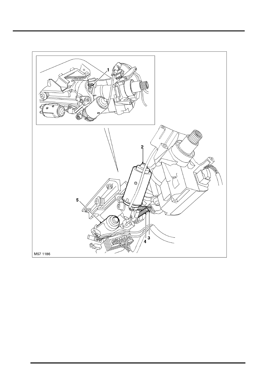
L322 Range Rover Steering Column Overview

STEERING
57-12
DESCRIPTION AND OPERATION
Column Adjustment
1 Vertical adjustment cam
2 Adjustment motor – tilt
3 Worm drive – tilt adjustment motor
4 Worm drive – reach adjustment motor
5 Adjustment motor – reach
The steering column is adjusted using a four way switch located on the LH side of the steering column, below the LH
column control switch.
The steering column adjustment is achieved by two electric motors and a column adjustment control unit on vehicles
without memory seats or by the memory seat ECU on vehicles with memory seats. Both motors are attached to the
lock housing / tilt head assembly and move the column via worm drive screws.
The reach adjustment motor drives a screw shaft which moves the column in and out for reach adjustment. The
adjustment is achieved by the two extruded aluminium sections which slide on one another. The tilt adjustment motor
also drives a screw shaft. This shaft is connected to a cam, which causes the tilt head to pivot, adjusting the column
angle.
