
Hydraulic Circuit Operation on L322 Range Rover
STEERING
57-22
DESCRIPTION AND OPERATION
Operation
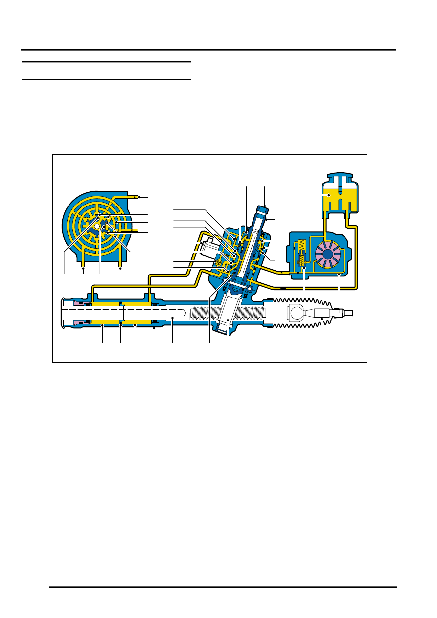
Hydraulic Circuit Operation
The following hydraulic circuits show power steering operation and fluid flow for the steering in a straight ahead,
neutral position and when turning right. The circuit diagram for turning left is similar to that shown for turning right.
Steering in Neutral Position
Circuit shows steering rotary valve in neutral position with the vehicle not moving.
1 Return fluid control groove
2 Radial groove
3 Feed fluid control groove
4 Radial groove
5 Axial groove
6 Feed fluid control edge
7 Feed fluid radial groove
8 Return fluid control edge
9 Return fluid chamber
10 Cut-off valve
11 Radial groove
12 Servotronic transducer
13 Feed fluid radial groove
14 Radial groove
15 Orifice
16 Balls
17 Compression spring
18 PAS fluid reservoir
19 Torsion bar
20 Valve rotor
21 Reaction piston
22 Reaction chamber
23 Centering piece
24 Pressure relief/flow limiting valve
25 PAS pump
26 Inner track rod
27 Pinion
28 Valve sleeve
29 Steering rack
30 Rack housing
31 Power assist cylinder – right
32 Piston
33 Power assist cylinder – left
M57 1184
24
1
2
3
4
5
6
7
8
9
9
10
11
12
13
14
15
16 17
19
18
20
21
22
25
26
27
28
29
30
31
32
33
23